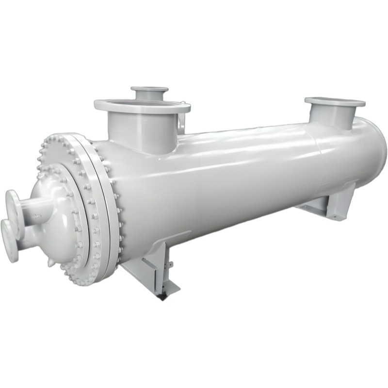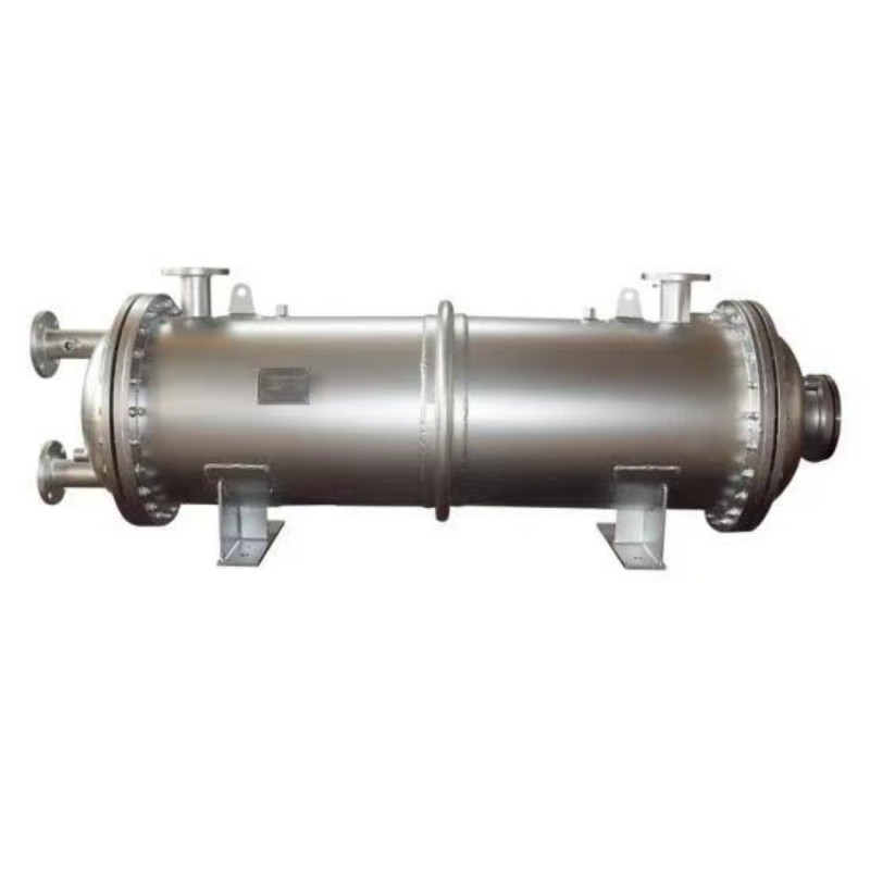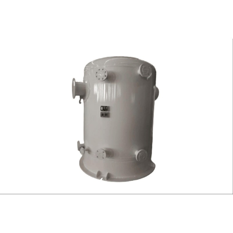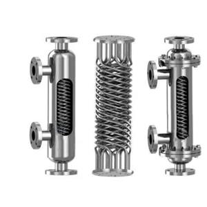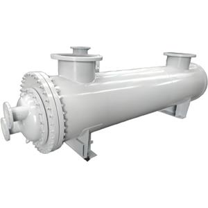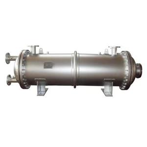
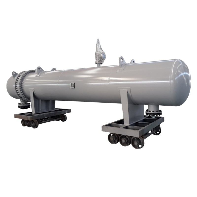
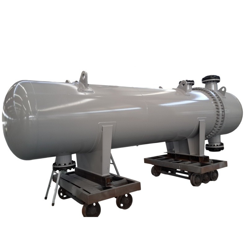
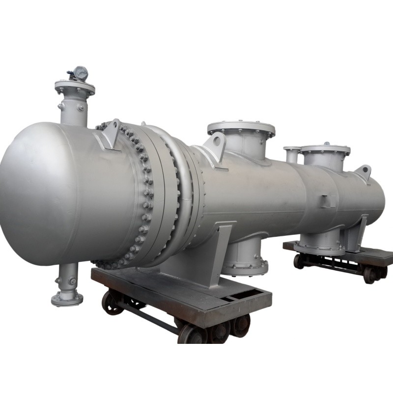
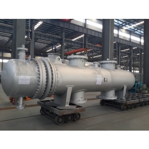
Industrial U Tube Heat Exchanger TEMA BEU AEU Shell Tube

- OEM/ODM
- CHINA
1.The l U-bend free telescopic structure has no structural restriction on the thermal expansion and contraction of the heat exchange tube. It can automatically offset the deformation difference caused by large temperature difference between tube and shell, completely eliminate thermal stress residue.
There is no equipment deformation and damage risk under long-term large temperature difference working conditions, which greatly reduces the failure rate and maintenance frequency of high-temperature difference industrial scenarios.
2.Optimized structural integration design minimizes the number of equipment sealing points, reduces the risk of high-pressure leakage caused by multi-point sealing failure, and significantly improves the overall high-pressure bearing capacity and sealing stability of the equipment.
It can adapt to long-term stable operation of high-pressure scenarios such as hydrogenation units, with lower failure rate and longer service cycle.
U-Tube Shell and Tube Heat Exchanger for High-Temperature, High-Pressure Refining and Power Service
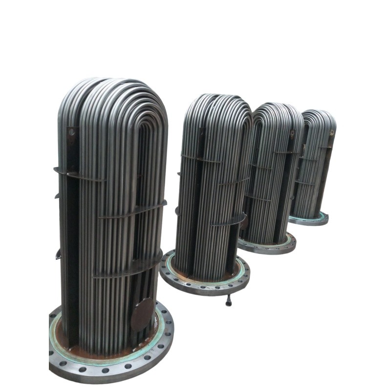
A U-tube heat exchanger is defined by a single tubesheet. Every tube is bent into a 180° return bend, so both tube ends terminate in the same tubesheet and the bundle is anchored at only one point. The opposite end floats free inside the shell. Under the TEMA nomenclature used in this page, the TEMA BEU / AEU U-Tube Exchanger configuration breaks down as follows: A = channel with removable cover, B = bonnet-type integral cover, E = single-pass shell, U = U-tube bundle. Selecting between AEU and BEU is a maintenance-access decision, not a thermal one: the A-type channel lets you inspect the tube ends without breaking the piping flange, while the B-type bonnet removes one gasketed joint from the pressure boundary at the cost of that access.
This industrial u-tube heat exchanger geometry is the correct engineering answer for one specific combination of conditions — high pressure, high temperature, a large temperature difference between shell-side and tube-side streams, and a tube-side fluid that stays clean.
User Decision Guidance: Core Industry Pain Points & Targeted Technical Solutions
Pain point 1 — Differential thermal expansion cracks tubesheets and tube-to-tubesheet joints.
In hydroprocessing units and power-plant feedwater service, the shell-side metal and the tube metal frequently operate several hundred degrees apart. In a fixed-tubesheet unit, that differential expansion is absorbed as axial stress in the tubes and bending stress in the tubesheet; the shell may yield, or the tube joints may lose preload and leak. The usual workaround is a shell expansion joint, which converts a stress problem into a fatigue problem — bellows have a finite cycle life and become a scheduled replacement item.
Corresponding Solution: each tube leg is free to expand independently, because the U-bend functions as a compliant element. The U-tube heat exchanger absorbs the entire shell-to-tube expansion differential internally, with no expansion joint required. There is no bellows to fatigue, no cycle count to track, and no thermal-stress term driving the tubesheet thickness calculation.
Pain point 2 — Hydrogen and H₂S service punishes every extra gasketed joint.
Refinery hydrotreating and hydrocracking streams combine high partial-pressure hydrogen with H₂S. Every gasketed closure is a potential ignition source and a confined-space entry permit waiting to be written.
Corresponding Solution: the TEMA BEU / AEU U-Tube Exchanger has one tubesheet instead of two, and no internal floating-head packing or internal gasket. Relative to a floating-head design, the number of pressure-boundary sealing points is materially lower, and the remaining joints sit on the outside of the shell where they can be visually monitored. Fewer sealing points mean fewer leak paths, lower fugitive-emission inventory, and better high-pressure performance.
Pain point 3 — Shell-side fouling silently destroys heat duty.
Fouling on the shell side of a sealed bundle cannot be inspected and cannot be mechanically removed. Duty loss then gets misdiagnosed as a process problem, and operators compensate by raising firing or steam flow.
Corresponding Solution:the bundle is removable. Pull the shell cover, withdraw the bundle, and the shell side — and the full tube outside surface — is accessible for high-pressure water jetting or chemical cleaning. Design duty is recoverable in a single turnaround rather than being written off over the asset life.
Real Industrial Application Scenarios
As a professional high-end thermal exchange equipment, the U-tube heat exchanger is mainly oriented to high-standard industrial extreme working conditions. Relying on thermal stress resistance, high-pressure sealing performance and convenient maintenance characteristics, it achieves stable application in multiple core industrial fields, and fully matches the production needs of Middle Eastern and European heavy industry enterprises.
Scenario 1: Petrochemical Hydrogenation Unit Production System
Petrochemical hydrogenation units belong to typical high-temperature and high-pressure industrial working conditions. In the hydrogenation reaction and thermal circulation link, the equipment needs to bear continuous high-pressure impact and large temperature difference heat exchange demand. The tube-side medium of the system is clean and free of dirt, which fully matches the applicable medium characteristics of the TEMA BEU / AEU U-Tube Exchanger. The U-shaped tube free telescopic structure eliminates thermal stress damage caused by frequent temperature changes in the hydrogenation system, and the detachable tube bundle structure supports regular cleaning of shell-side reaction impurities, ensuring long-term stable and efficient operation of the hydrogenation unit heat exchange system and avoiding production shutdown caused by equipment failure.
Scenario 2: Large-Scale Power Station Thermal Cycle System
In the steam-water heat exchange and waste heat recovery system of thermal power stations, there is an extremely large temperature difference between the high-temperature steam on the shell side and the circulating medium on the tube side. Conventional heat exchange equipment is prone to structural deformation and efficiency attenuation under long-term large temperature difference operation. The industrial u-tube heat exchanger relies on its unique thermal stress elimination structure to adapt to the extreme temperature difference working environment of power stations. The few sealing points design ensures the safety and stability of the high-pressure thermal cycle system, meets the 24-hour continuous operation demand of power station equipment, and effectively reduces the energy consumption and maintenance cost of power station waste heat recovery.
Scenario 3: High-Precision Industrial Thermal Exchange System with Clean Tube-Side Medium
In fine chemical, energy equipment and other industrial scenarios with clean tube-side medium and no dirt fouling, the U-Tube Shell and Tube Heat Exchanger gives full play to its structural advantages. The tube-side medium will not scale and block, maintaining long-term stable heat transfer efficiency. The shell side can be disassembled and cleaned regularly to cope with trace impurities in the industrial circulating medium. The high-pressure resistant sealing structure is suitable for medium and high-pressure industrial circulation systems, providing efficient and low-consumption thermal exchange support for various high-standard industrial production lines.
FAQ
Q1: What working conditions are U-tube heat exchangers most suitable for, and what scenario restrictions exist?
This series of U-tube heat exchanger is specially designed for high temperature, high pressure and large tube-shell temperature difference industrial working conditions, and is widely applicable to hydrogenation units, power station thermal cycle systems and other heavy industrial scenarios. The core applicable limitation is that the tube-side medium needs to be clean and free of dirt and fouling; it is not recommended for working conditions with serious tube-side scale and particle impurities, which can avoid tube-side blockage and ensure long-term stable heat transfer efficiency of the equipment.
Q2: What are the core differences between TEMA BEU / AEU U-Tube Exchanger and ordinary U-tube heat exchangers?
TEMA BEU / AEU U-Tube Exchanger is manufactured in accordance with the highest international TEMA industry standards, with standardized structural size, pressure resistance design and sealing process. Compared with ordinary customized U-tube heat exchangers, it has more stable high-pressure performance, more reasonable thermal stress release structure, and higher industrial matching. It is the preferred standard equipment for high-end industrial projects in Europe, America and the Middle East, and has better compatibility with international industrial supporting systems.
Q3: Is the shell side of the industrial u-tube heat exchanger convenient for daily maintenance and cleaning?
It has excellent maintenance convenience. The product adopts an integral extractable tube bundle design. In the daily maintenance process, the entire tube bundle can be directly pulled out from the equipment shell without disassembling the shell and pipeline structure, realizing full-range dead-angle-free cleaning of the shell side. This design greatly shortens the equipment maintenance cycle, reduces maintenance difficulty, and avoids production shutdown loss caused by long-time equipment maintenance.
Q4: Can this U-Tube Shell and Tube Heat Exchanger adapt to long-term high-pressure continuous operation?
Yes. The product optimizes the structural layout of sealing points on the basis of U-tube design, greatly reducing the number of assembly sealing interfaces. Fewer sealing points effectively reduce the risk of high-pressure leakage and sealing aging failure. The overall pressure-resistant structure is optimized for industrial high-pressure working conditions, which can withstand long-term continuous high-pressure impact, maintain stable sealing performance and operating state, and fully meet the 24-hour continuous operation needs of industrial high-pressure systems such as hydrogenation units.
Q5: Is customized service support available for the industrial u-tube heat exchanger?
We support standardized customized services for industrial working conditions. According to the actual temperature difference, pressure parameter, medium characteristics and on-site installation space of the user's industrial scenario, we can adjust the tube bundle specification, shell size, heat exchange area and interface standard of the U-tube heat exchanger. All customized products are manufactured in accordance with TEMA standard specifications to ensure that the customized equipment maintains consistent high pressure resistance, thermal stress elimination and easy maintenance performance, meeting the personalized needs of different industrial projects in Europe, America and the Middle East.