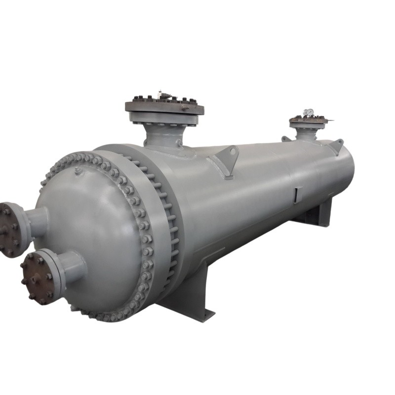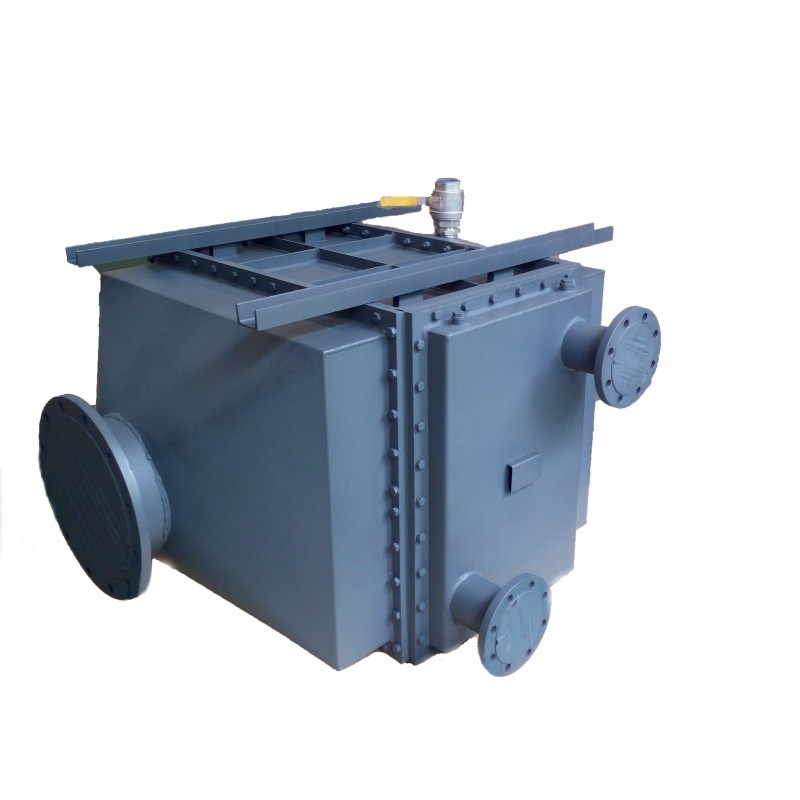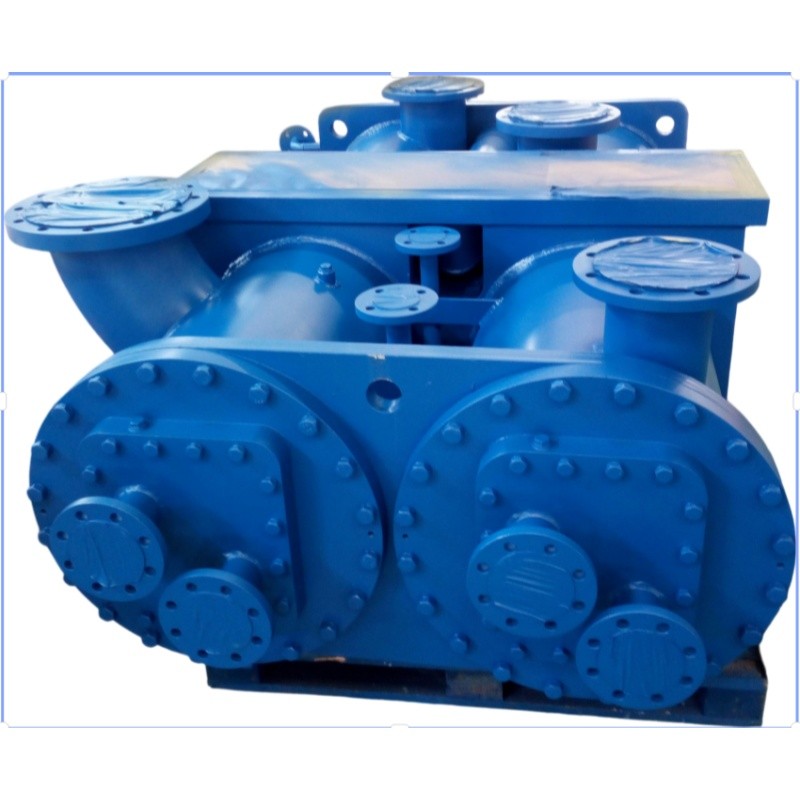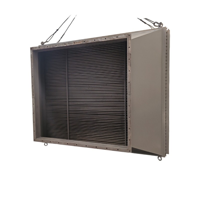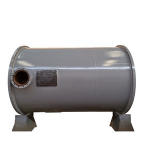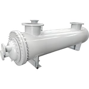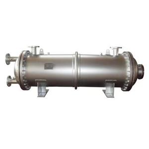
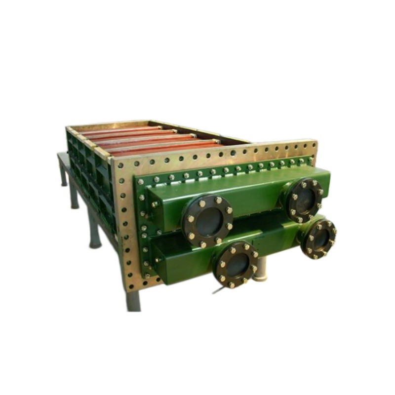
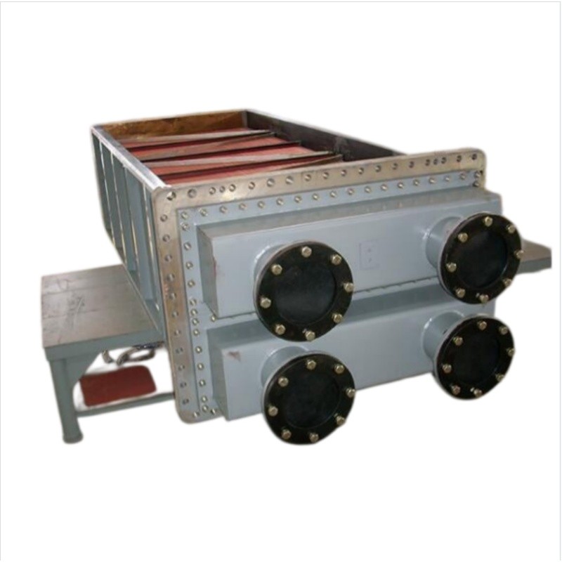
Generator Hydrogen Cooler Shell Tube Hydrogen Cooled Type

- OEM/ODM
- CHINA
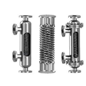
1.Performance: Self-developed curved vortex generator combined with anti-clogging turbulence fins increases heat transfer efficiency by 10.9%, delivering precise temperature control, energy savings, and fouling resistance.
2.Structure: Expanded-and-welded joint for media isolation, with curved turbulence design tailored to operating conditions.
3.Reliability: Customizable helium leak detection, dedicated natural frequency inspection, hydrostatic pressure testing, and non-destructive examination (NDE).
4.Maintainability: Modular pull-out design allows servicing without disassembling the main generator, reducing downtime and associated revenue loss.
Generator Hydrogen Cooler Shell Tube Hydrogen Cooled Type
Parameter | Specification / Material Options |
Shell & Tube Side | Shell Side:Water |
Tube Side:Hydrogen (H2) | |
Heat Exchange Tube | BFe10-1-1 (CuNi 90/10) |
BFe30-1-1 (CuNi 70/30) | |
T2 (Pure Copper) | |
S30403 / S31603 (TP304/TP316L SS) | |
S22053 (Duplex 2205 SS) | |
Tubesheet | Carbon Steel |
Stainless Steel | |
Copper &Copper-Steel Clad Plate | |
Water Box (Channel) | Carbon Steel |
Stainless Steel | |
Fin Material | Aluminum Fins |
Copper Fins |
Note: All materials conform to ASTM/ASME standards. S30403/S31603 correspond to TP304L/TP316L. S22053 corresponds to Duplex 2205.
Hydrogen Cooler for Generator: Shell-and-Tube Cooling Solutions for 1000MW-Class Thermal, Nuclear, and Gas Turbine Generators
Why Generator Hydrogen Cooler Failures Cost More Than the Equipment Itself
Large synchronous generators rely on hydrogen as the primary cooling medium because it offers 7–10 times higher thermal conductivity than air and reduces windage losses inside the rotor enclosure. However, this advantage collapses the moment the hydrogen cooler for generator underperforms. Three failure modes dominate maintenance logs across Middle Eastern and European power plants:
Pain Point 1 — Heat Exchanger Fouling and Capacity Degradation. Cooling water in Gulf-region plants carries elevated dissolved solids and suspended particulates. Conventional straight-fin bundles develop laminar boundary layers along tube walls, allowing mineral scale and biofilm to accumulate. As fouling thickens, the logarithmic mean temperature difference (LMTD) shrinks, hydrogen return temperature rises, and the generator's insulation class is progressively derated.
The solution lies in curved vortex-generator fins combined with anti-clogging turbulence fins. The curved profile induces secondary flow (Dean vortices) that disrupts the thermal boundary layer at the tube wall, while the anti-clogging geometry prevents particulate lodging in fin gaps. Independent testing confirms a 10.9% improvement in overall heat transfer coefficient compared to standard fin bundles, meaning the unit maintains design hydrogen outlet temperature even as water-side fouling resistance increases.
Pain Point 2 — Hydrogen Leakage Through Tube-to-Tubesheet Joints. Hydrogen's molecular diameter (2.89 Å) makes it the smallest diatomic molecule; any micro-gap in a joint becomes a leak path. Inadequately expanded tubes suffer from differential thermal expansion fatigue — the tube and tubesheet expand at different rates during load cycling, progressively loosening the mechanical joint.
This product uses an expanded-and-welded dual-seal construction. The mechanical expansion creates radial interference that seals against process pressure, while the circumferential weld provides a metallurgical barrier that is immune to thermal-cycling relaxation. Together they form a zero-leakage structure validated by custom helium leak detection — helium's molecular size (2.6 Å) is even smaller than hydrogen, so a helium-certified joint guarantees hydrogen integrity.
Pain Point 3 — Vibration-Induced Tube Failure Under Seismic and Transient Conditions. Generator coolers operate in an environment dominated by electromagnetic vibration (100 Hz for 50 Hz grids) and potential seismic excitation. Tubes that are not individually analyzed for natural frequency can enter resonance, causing fretting wear at support plates and eventual tube rupture.
This design subjects every bundle to dedicated natural frequency inspection, ensuring tube the excitation spectrum by a margin of at least 20%. Combined with hydrostatic pressure testing and non-destructive examination (NDE) of all welds, the cooler is engineered for the mechanical shock and vibration profile of 1000MW-class thermal, nuclear, and gas turbine generators.
Application Environments
1.Thermal Power Plant — 1000MW Coal-Fired Subcritical/Supercritical Unit. Installed in the generator hydrogen circuit of a 1000 MW steam turbine generator, the cooler removes rotor and stator winding losses (typically 3–5 MW of heat). The modular pull-out bundle allows inspection during the annual outage without removing the generator end shield — the cooler is slid out on its rails, tubes are brushed or chemically cleaned, and the bundle is reinserted. Total cooler maintenance window: under 8 hours.
2.Nuclear Power Plant — Steam Turbine Generator Island. In nuclear applications, the hydrogen cooler for synchronous generator operates in a controlled-radiation environment where every maintenance entry carries ALARA (As Low As Reasonably Achievable) dose implications. The zero-leakage construction minimizes hydrogen ingress into containment, and the helium-tested joints reduce the frequency of leak investigations. The natural-frequency-certified tube bundle withstands the vibration profile of large four-pole nuclear generators.
3.Gas Turbine Combined-Cycle Plant — Hydrogen Cooled Generator for Gas Turbine. In combined-cycle installations, the generator is directly coupled to a gas turbine (e.g., 300–500 MW class F or H turbine). Start-stop cycling is more frequent than in base-load thermal plants, subjecting the cooler to thermal transients. The expanded-and-welded tube joints resist thermal-fatigue loosening, and the anti-clogging fins handle the variable cooling water flow rates typical of cycling plants.
Frequently Asked Questions
Q1: Can the cooler be customized for our specific generator model and cooling water chemistry? Yes. The tube material is selected based on your cooling water analysis — BFe10-1-1 or BFe30-1-1 cupronickel for seawater/brackish service, T2 copper for maximum thermal conductivity in clean freshwater, S31603 or S22053 duplex stainless for high-chloride or sour water. Tube box and tube sheet materials are similarly configurable (carbon steel, stainless steel, or copper-steel clad plate). Provide the generator OEM model, hydrogen flow rate, inlet/outlet temperature targets, and cooling water data sheet for a thermal-mechanical design proposal.
Q2: What is the typical delivery lead time for a custom unit? Lead time depends on material selection and unit size. Standard carbon-steel/stainless configurations with common tube materials (S30403, T2) have shorter lead times; cupronickel (BFe30-1-1) and duplex (S22053) tubes require longer material procurement. All units undergo the full four-stage verification (helium leak, natural frequency, hydrostatic, NDE) before shipment, which is included in the schedule. Contact the sales engineering team with your project timeline for a committed delivery date.
Q3: How is the cooler maintained without disassembling the generator? The bundle uses a modular pull-out (抽拉) construction mounted on internal rails. During a planned outage, the cooler's water-side headers are disconnected, the bundle is slid out axially, and tube cleaning (mechanical brushing or chemical circulation) is performed externally. The generator rotor, end caps, and hydrogen seals remain undisturbed. This design reduces cooler-related outage time from multiple days (for non-modular designs) to a single shift.
Q4: What testing documentation ships with the unit? Each unit is delivered with the full set of quality records: helium leak detection report, natural frequency inspection report, hydrostatic pressure test chart, NDE reports for all welds, material test certificates (MTC) per EN 10204 3.1 or equivalent, and dimensional inspection records. These documents support client receiving inspection and regulatory compliance for power plant commissioning.
Q5: Is the cooler compatible with existing generator hydrogen sealing and control systems? The shell-and-tube hydrogen cooler for generator is designed as a drop-in or engineered replacement compatible with standard generator hydrogen circuits (typically 0.3–0.6 MPa g hydrogen pressure, depending on generator OEM). The shell-side (hydrogen) connections and tube-side (water) connections are configured to match existing piping. For retrofits, provide the existing cooler's general arrangement drawing and connection schedule; the engineering team will design the replacement to match interface dimensions while upgrading the internal heat transfer and sealing technology.