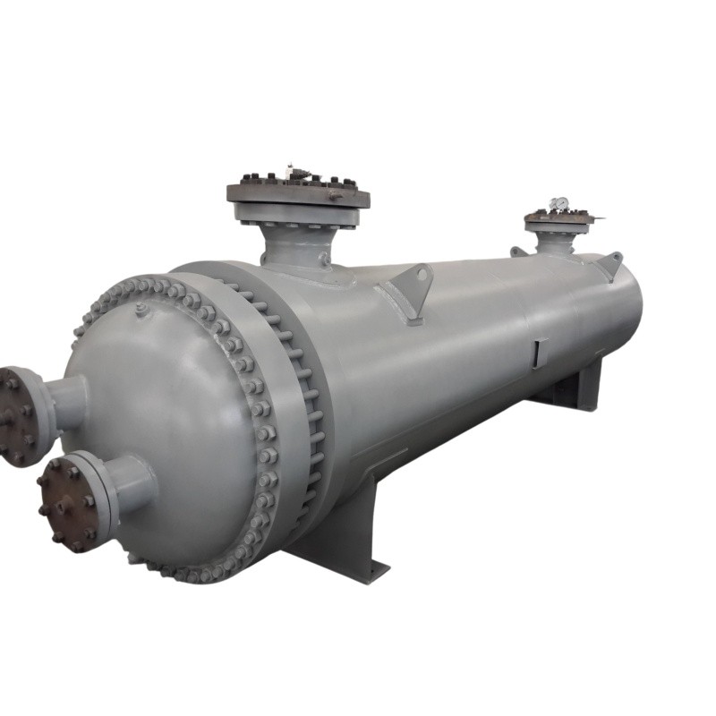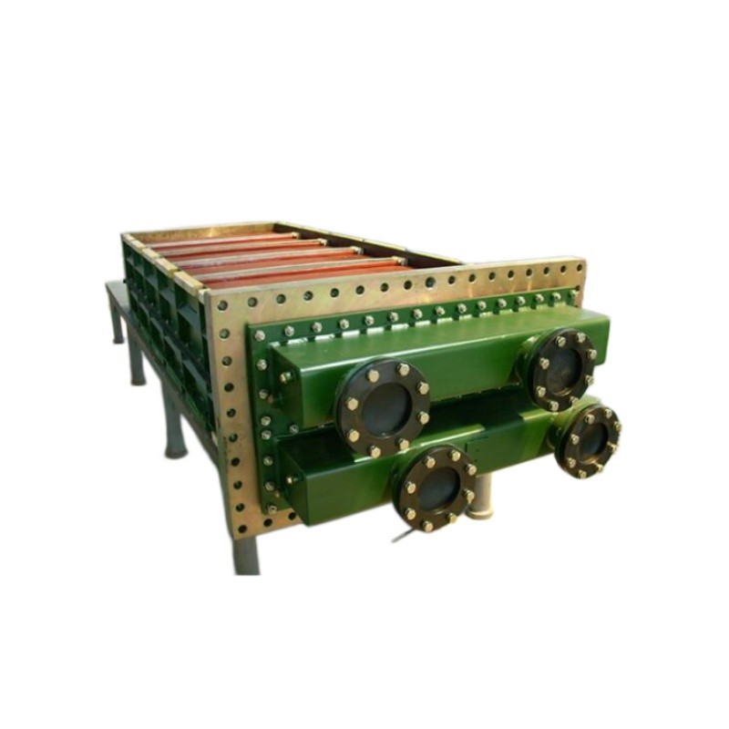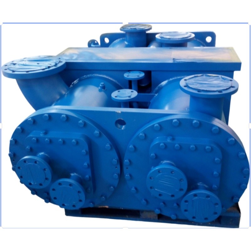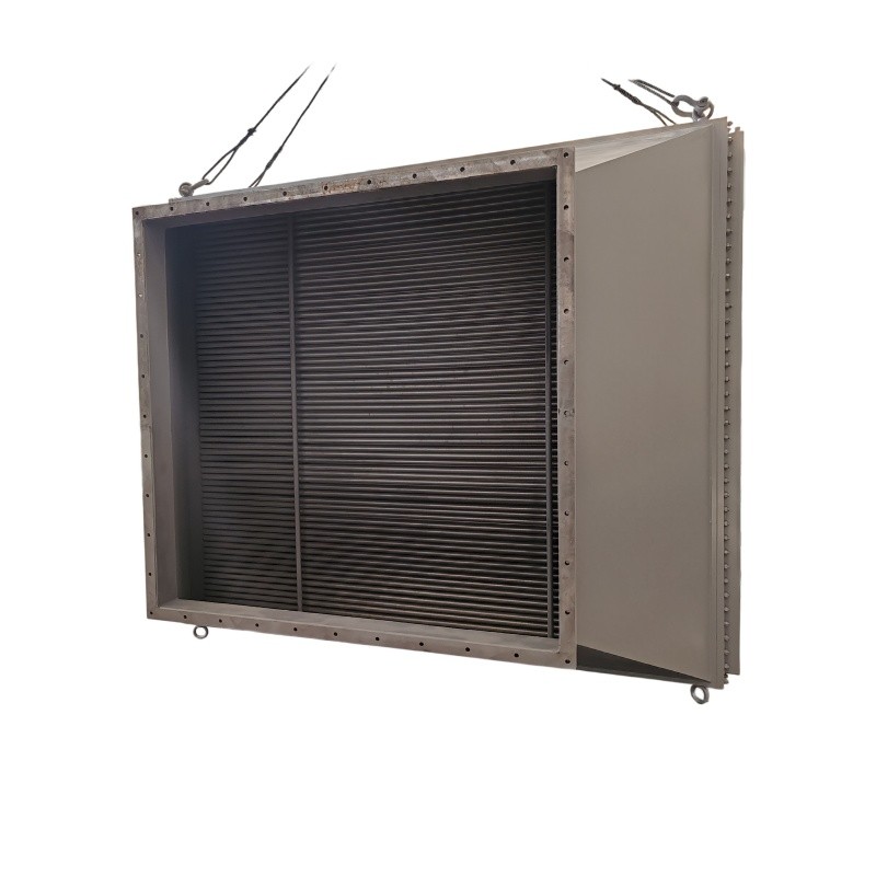
Industrial Waste Heat Recovery System Unit Package HRSG

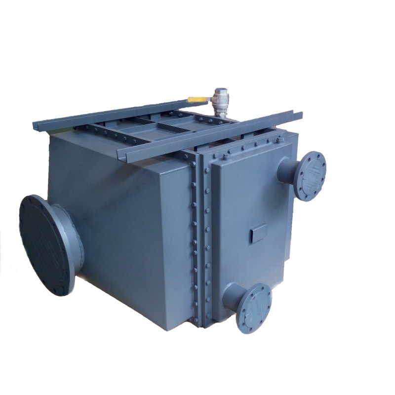
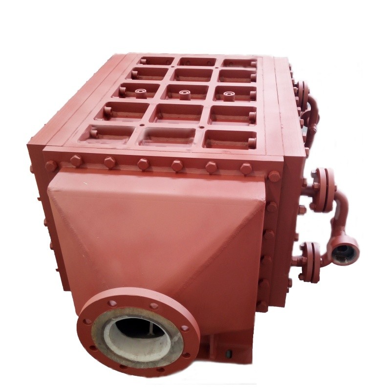
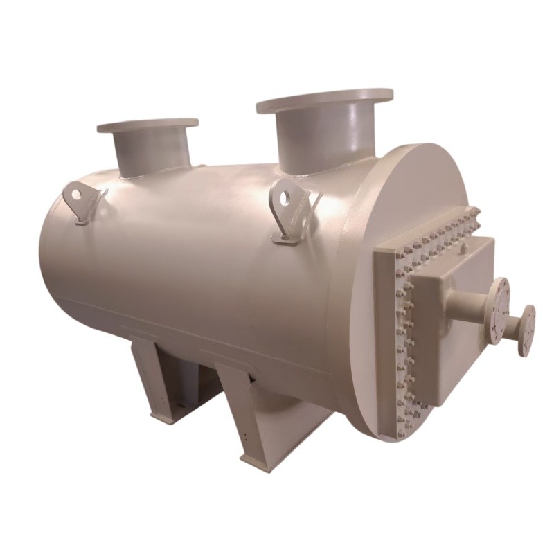
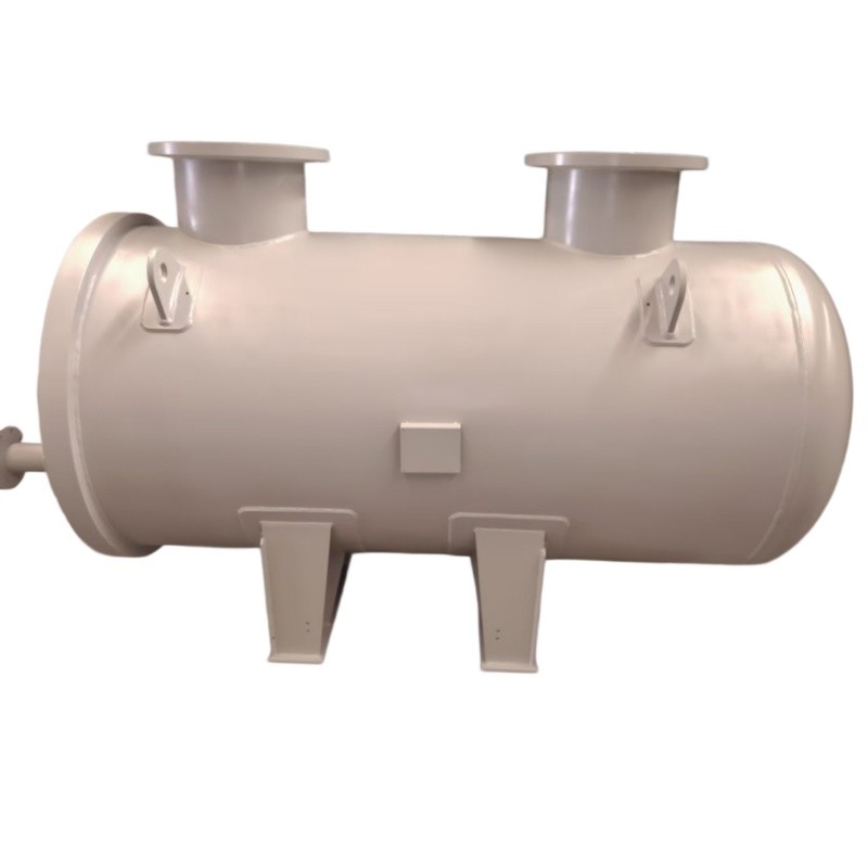
- OEM/ODM
- CHINA
1.Superior resistance to seawater and treated water corrosion.
2.Higher yield strength at elevated temperatures compared to mild steel.
3.Verified weld integrity reduces the risk of catastrophic failure.
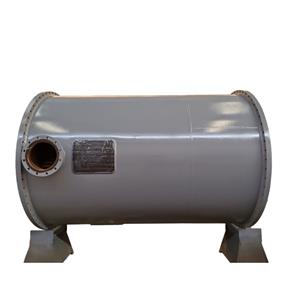
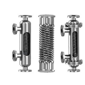
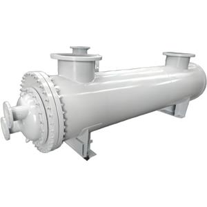
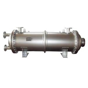
4.Adopting a professional finned tube enhanced heat exchange structure, this unit delivers 343㎡ total heat exchange . The multi-dimensional expanded contact area enables full-coverage medium heat exchange and greatly boosts waste heat recovery efficiency. For continuously operating industrial plants, it delivers superior annual energy savings and better energy-saving performance than conventional equipment.
Finned Tube Waste Heat Recovery Unit – Engineered for High-Efficiency Thermal Transfer in Industrial Systems
| Parameter Category | Shell Side | Tube Side |
| Working Pressure MPa(A) | 0.796 | 1 |
| Design Pressure MPa(G) | 1.2 | 1.2 |
| Working Temperature °C | 58/17 | 9/23 |
| Design Temperature °C | 120 | 80 |
| Medium | Air | Chille-nter |
| Medium Properties | Non-toxic,Non-flammable | Non-toxic,Non-flammable |
| Material for Main Pressure-bearing Components | Q345R | Q345R,BFe10-1 |
| Corrosion Allowance mm | 2 | 2 |
| Weld Joint Coefficient | 0.85 | 0.85 |
| Volume m3 | 1.6 | 0.2 |
| Heat Exchange Area m2 | 343 | |
| Design Service Life | 10 years | |
| Lifting Weight Kg | ≈2200 | |
| Operating Weight Kg | ≈2500 | |
| Water‑filled Weight Kg | ≈4000 | |
Why Most Waste Heat Recovery Systems Underperform – And How This Unit Solves It
Industrial operators across the Middle East and Europe face three recurring challenges when deploying a waste heat recovery system:
Pain Point 1: Corrosion and Material Degradation in Continuous Operation
Many heat recovery units fail prematurely because their pressure-bearing components are manufactured from standard carbon steel, which degrades under sustained thermal cycling and moisture exposure. This unit addresses the issue by using Q345R steel for all primary pressure-bearing elements on both shell and tube sides, paired with a BFe10-1-1 copper-nickel alloy on the tube side. The BFe10-1-1 alloy is specifically selected for its resistance to water-side corrosion in closed-loop chilled water circuits. A corrosion allowance of 2 mm is built into both sides, meaning the unit retains structural integrity well beyond its 10-year design life even under aggressive operating conditions.
Pain Point 2: Pressure Boundary Failures Under Variable Load
A common failure mode in field-deployed flue gas heat recovery units is the inability to handle pressure transients during startup, shutdown, or load swings. This unit is rated with a shell-side design pressure of 1.2 MPa(G) and a tube-side design pressure of 1.2 MPa(G), while operating at 0.796 MPa(A) and 1 MPa(A) respectively. This provides a substantial safety margin — approximately 50% overpressure capacity on the shell side — ensuring the pressure boundary remains intact during transient events without requiring frequent safety valve actuation.
Pain Point 3: Excessive Downtime Due to Heavy Maintenance Requirements
With an equipment dry weight of approximately 2,200 kg and a running weight of approximately 2,500 kg, this unit is engineered as a compact, skid-mounted package. The total flooded weight is approximately 4,000 kg, which allows it to be lifted and positioned with standard site cranes. The compact footprint — derived from a shell-side volume of 1.6 m³ and tube-side volume of 0.2 m³ — reduces the spatial and structural support requirements at the installation site, cutting installation time and civil works costs.
Real-World Application Scenarios
This waste heat recovery package is designed for industrial flue gas and air waste heat recovery working conditions, and is widely applicable to high-energy-consumption industrial scenarios in the Middle East, Europe and other regions. Relying on stable pressure and temperature resistance, high-efficiency heat exchange and safe and non-toxic medium adaptation characteristics, it realizes efficient waste heat recycling and energy-saving consumption reduction in multiple industrial fields.
1 Petrochemical Industrial Flue Gas Waste Heat Recovery
In the petrochemical production bases widely distributed in the Middle East, a large amount of high-temperature flue gas and waste air will be generated in the refining and chemical processing links. The traditional exhaust method will cause a lot of heat energy loss. Our Finned Tube Waste Heat Recovery Unit can collect the waste heat of exhaust air and flue gas through the shell-side air heat exchange channel, and realize heat recycling through tube-side chilled water circulation. The equipment adapts to the continuous and stable operation requirements of petrochemical production lines, with non-toxic and non-flammable medium operation, no safety and environmental protection risks, and effectively reduces the comprehensive energy consumption of petrochemical production.
2 Heavy Machinery and Compressor Cooling
In facilities with large air compressors or gas turbines, the discharge air temperature can reach 58°C. This Waste Heat Recovery Unit acts as an intercooler or aftercooler, reducing the air temperature to 17°C. This specific temperature drop is essential for improving the efficiency of downstream pneumatic tools and reducing moisture carryover in the air lines.
3 Process Ventilation Heat Recovery: In manufacturing plants where hot exhaust air (58°C) is vented, this unit captures the thermal energy. By passing the air over the 343 m² finned tube bundle, the heat is transferred to a chilled water loop. This not only cools the workspace but also provides a source of pre-warmed water for other processes, reducing the load on primary boilers.
4 HVAC and Data Center Cooling: For large-scale cooling applications, this Heat Recovery Steam Generator alternative uses chilled water (9°C inlet) to absorb heat from the air stream. The 1.6 m³ shell volume is designed to handle high air flow rates, making it suitable for main plant ventilation systems where maintaining a 17°C outlet is critical for equipment protection.
Frequently Asked Questions (FAQ)
Q1: What industrial working conditions is this Finned Tube Waste Heat Recovery Unit suitable for?
This equipment is mainly applicable to flue gas waste heat recovery and air waste heat recovery scenarios in petrochemical, manufacturing, industrial park central air conditioning and other industries. It adapts to the working conditions with air and chilled water as the medium, working pressure within 1MPa and working temperature within 120℃, and is widely used in high-energy-consumption industrial enterprises in Europe, the Middle East and other regions.
Q2: Can the equipment parameters be customized according to customer working conditions?
On the premise of meeting Class I pressure vessel safety standards, we can carry out targeted fine-tuning of individual parameters such as medium matching and partial heat exchange scheme according to the actual working condition requirements of customers. The core safety parameters such as design pressure, corrosion margin and welding coefficient uniformly implement international standard specifications to ensure equipment operation safety.
Q3:How does the 2 mm corrosion allowance benefit the operation?
A: The 2 mm corrosion allowance is a design margin added to the calculated wall thickness. Over the 10-year design life, if minor corrosion occurs on the shell (Q345R) or tube surfaces, this 2 mm layer protects the structural integrity of the pressure boundary. It ensures the vessel remains safe even in moderately corrosive industrial atmospheres.
Q4:Is this unit compatible with existing heat recovery steam generator installations?
Yes. The unit can function as a supplementary heat recovery stage in systems where a primary heat recovery steam generator handles high-temperature gas streams. Its lower design temperature rating (120℃ shell side) makes it suitable for low-temperature exhaust gas applications downstream of the main HRSG.
Q5: Are spare parts and replacement tubes available?
The tube-side material specification (BFe10-1-1) and shell-side material (Q345R) are standard industrial materials with established supply chains. Replacement tube bundles and pressure-boundary components can be fabricated to the original design specifications. Specific spare parts availability and lead times should be confirmed with the manufacturer at the time of order.