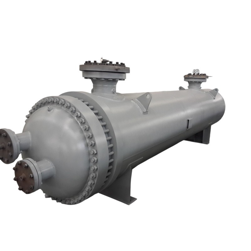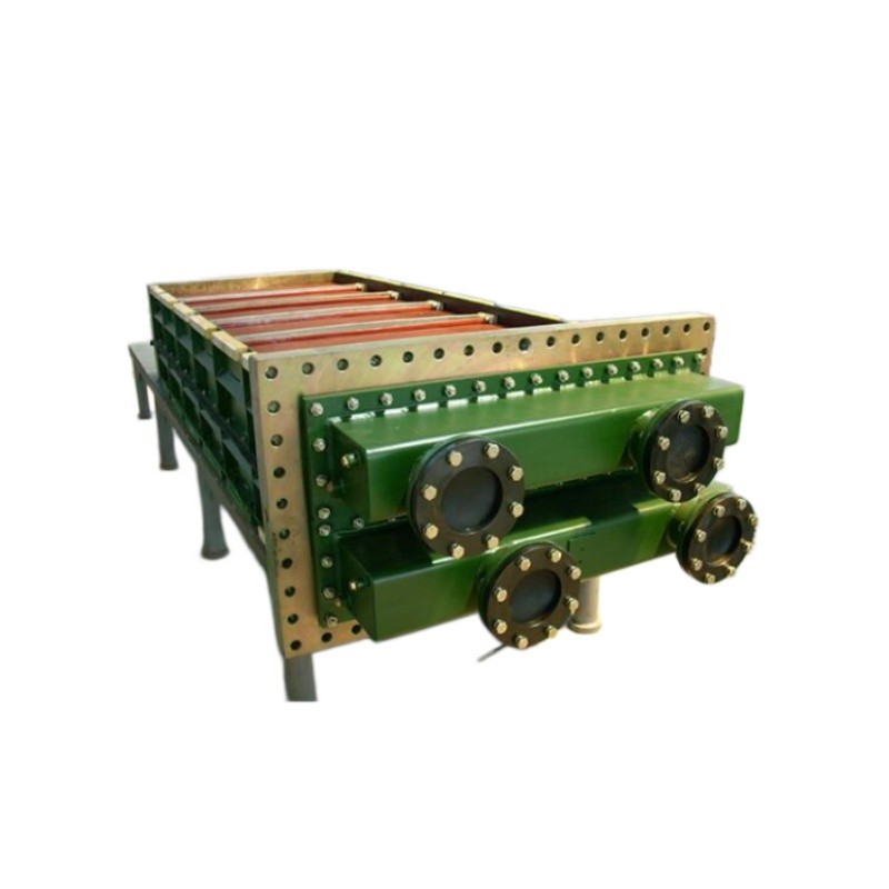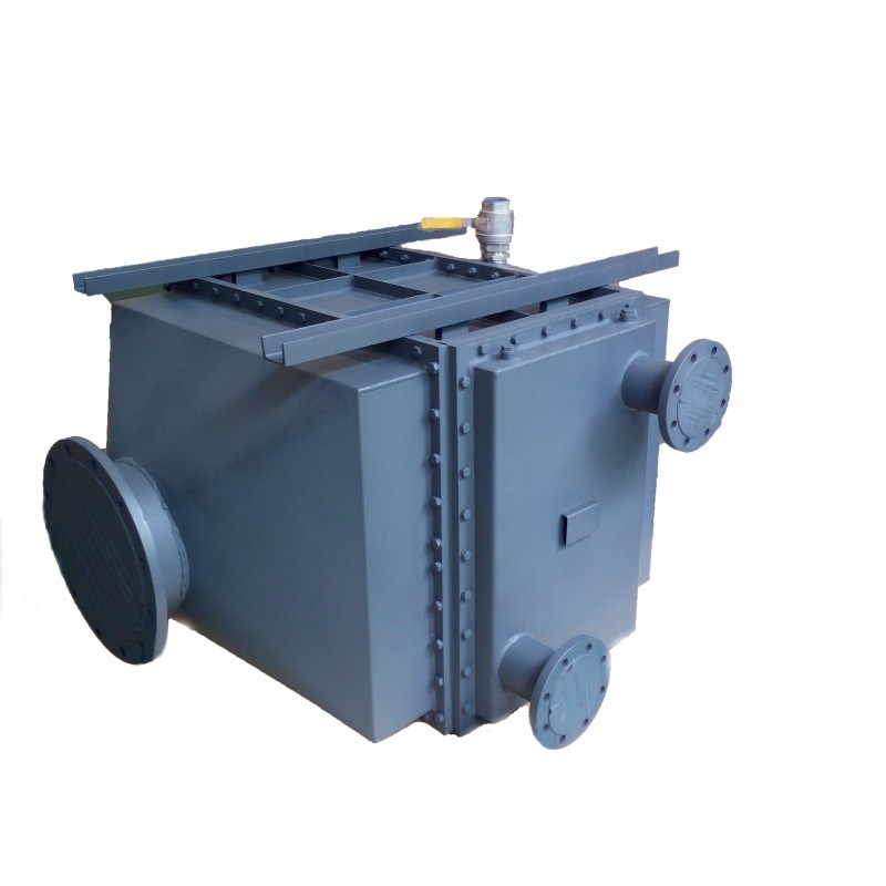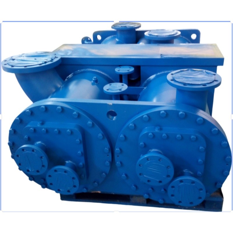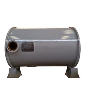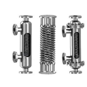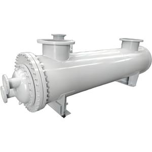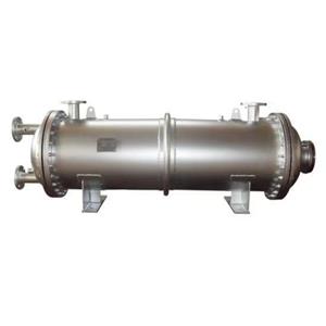
Industrial Air Heater Finned Tube Steam Heating Equipment

- OEM/ODM
- CHINA
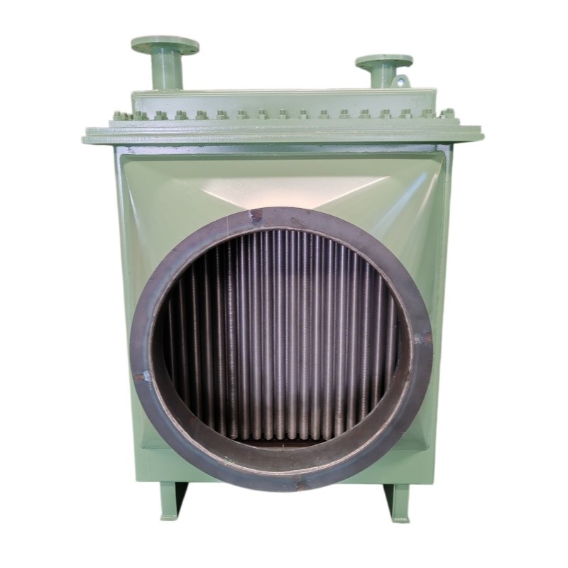
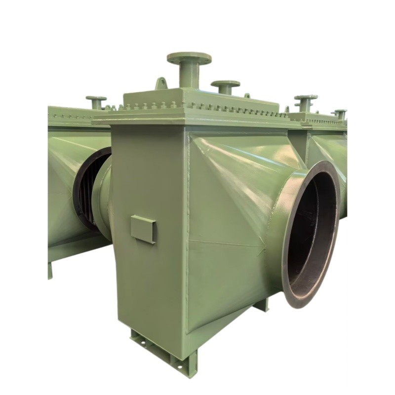
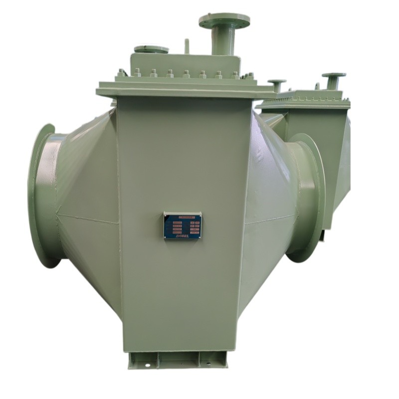
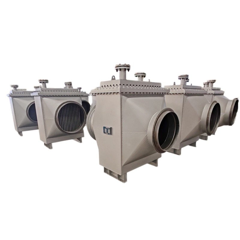
1.Gas-liquid two-phase heat transfer for high-temperature process tail gas waste heat recovery.
2.Compact 4–6 m² footprint with 124 m² finned tube heat transfer area per unit — quantifiable savings in installation cost and operating energy.
3.Extended fin surface enables optimal flow velocity with an actual pressure drop of just 700 Pa, delivering superior dust-laden gas adaptability.
4.Customizable fin spacing with online soot blowing — routine maintenance completed without extracting the tube bundle.
5.Shell-side design temperature of 150°C with zero gasket aging risk.
Industrial Air Heater Finned Tube Steam Heating Equipment
Parameter | Shell Side | Tube Side |
Medium | Tail Gas | Circulating Water |
Temperature | ||
Inlet Temperature | 130°C | 35°C |
Outlet Temperature | 55°C | 45°C |
Design Temperature | 150°C | 80°C |
Flow Rate | 22,000 m3/h | 36 t/h |
Design Pressure | Atmospheric Pressure | 0.6 MPa(3) |
Allowable Pressure Drop | 800 Pa | 35 kPa |
Actual Pressure Drop | 700 Pa | 30 kPa |
Heat Transfer Area | 124 m2 | |
Why Your Tail Gas Treatment System Needs Re-Selection — Three Overlooked Decision Pain Points
Pain Point 1: Direct Discharge of High-Temperature Tail Gas — Dual Pressure from Energy Waste and Environmental Penalties
In petrochemical, chemical, and metallurgical processes, process tail gas at approximately 130°C is typically discharged directly after simple treatment. At a flow rate of 22,000 m³/h, the sensible heat discharged per hour exceeds 400 kW, equivalent to approximately 3.5 million kWh of thermal energy wasted annually — a quantifiable economic loss against the backdrop of rising energy costs in the Middle East. Meanwhile, high-temperature tail gas discharge also poses compliance risks from VOC exceedance and thermal pollution. Environmental regulations in Europe and North America already impose explicit requirements on discharge temperatures and heat recovery efficiency.
Solution: This Industrial Air Heater employs a finned tube heat transfer structure that efficiently transfers the sensible heat of high-temperature shell-side tail gas (130°C → 55°C) to tube-side circulating water (35°C → 45°C), delivering a heat recovery load of approximately 420 kW per unit. The 124 m² heat transfer area enables continuous heat exchange for large-volume gas within a compact shell, with the tail gas outlet temperature stably controlled at 55°C to meet the temperature requirements of downstream treatment processes. For Middle Eastern B2B buyers, this Finned Tube Air Heater converts otherwise wasted thermal energy into usable hot water resources for process heating, wash water preheating, or lithium bromide absorption chiller drive.
Pain Point 2: Bulky Equipment for High-Volume Gas Heat Exchange — The Dilemma Between Installation Space and Pressure Drop Control
When handling gas flow rates on the order of 22,000 m³/h, conventional bare-tube shell-and-tube heat exchangers require extremely large shell diameters and tube bundle counts to maintain reasonable gas-side velocity, often exceeding available on-site installation space. If equipment dimensions are forcibly reduced, elevated gas velocity causes pressure drop to spike, induced draft fan power consumption increases substantially, and operating costs spiral out of control. Many projects only discover during commissioning that the actual pressure drop far exceeds the allowable value, forcing retrofits with variable-frequency fans or bypass piping — additional investment that is difficult to control.
Solution: This Finned Tube Air Heater uses fin-extended heating surfaces on the tube exterior, increasing the gas-side heat transfer area by 3–5 times compared to bare tubes, allowing significantly reduced shell dimensions under the same heat duty. During the design phase, flow field simulation was performed for the 22,000 m³/h tail gas flow rate, controlling the shell-side actual pressure drop at 700 Pa (allowable value: 800 Pa), providing a pressure drop margin of 12.5% without requiring additional induced draft fan power. The tube-side circulating water actual pressure drop is 30 kPa (allowable value: 35 kPa), similarly retaining a safety margin. The compact structure of this Air Heater allows installation within existing pipe racks or unit frames, avoiding civil engineering modifications.
Pain Point 3: Dust-Laden Tail Gas Causes Erosion and Blockage of Heat Transfer Surfaces — Severe Losses from Unplanned Shutdowns
Industrial tail gas typically contains catalyst dust, coke powder, or particulate matter. Deposition on heat transfer tube surfaces increases thermal resistance and degrades heat exchange efficiency. Conventional bare-tube heat exchangers have narrow tube spacing; when dust-laden gas passes through, bridging blockage easily forms between tubes, and erosion concentrates on the first row of windward tubes, where local thinning can lead to tube wall perforation. For continuously operating chemical plants, a single unplanned shutdown caused by heat exchanger blockage or leakage can result in losses ranging from tens of thousands to hundreds of thousands of dollars.
Solution: The finned tubes of this Industrial Air Heater employ an optimized inline or staggered arrangement (the specific configuration is determined by operating condition calculations), with fin spacing designed according to tail gas dust loading to prevent particulate bridging. The shell-side atmospheric pressure design reduces sealing complexity and leakage risk, and the 150°C design temperature provides a 20°C margin for tail gas temperature fluctuations. When heat transfer surface ash accumulation requires cleaning, online steam or compressed air purging can be performed through shell-side purge ports without shutdown or disassembly. The finned tube material and wall thickness of this Steam Air Heater series can be customized based on tail gas dust characteristics, structurally extending equipment service life under dust-laden operating conditions.
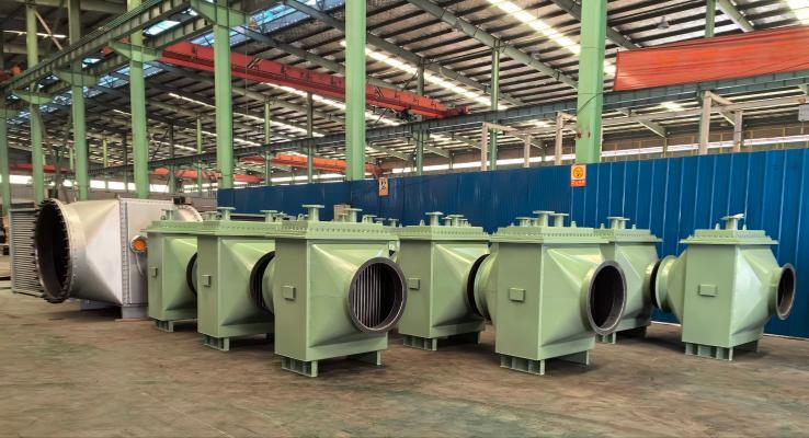
Real-World Application Scenarios — How the Equipment Performs On-Site
Scenario 1: Tail Gas Waste Heat Recovery Unit at a Petrochemical Plant
In the tail gas treatment system of a petrochemical facility along the Persian Gulf coast, process tail gas after upstream scrubbing reaches approximately 130°C at a flow rate of 22,000 m³/h, originally designed for direct discharge to the stack. The plant is located on the edge of a desert, with summer ambient temperatures consistently above 45°C, and circulating water supplied by a cooling tower at a feed temperature of 35°C. This Finned Tube Air Heater is installed on the pipe rack between the tail gas fan outlet and the stack. The shell side carries tail gas (atmospheric pressure, actual pressure drop 700 Pa), and the tube side carries circulating water (36 t/h, actual pressure drop 30 kPa). After commissioning, the tail gas outlet temperature stabilized at 55°C, the circulating water outlet temperature reached 45°C, and the recovered hot water was used for winter heating and wash water preheating in the unit area, delivering significant annual thermal energy cost savings. The interval before the first fin purge exceeded 12 months.
Scenario 2: Process Gas Cooling and Heat Recovery at a Chemical Plant
In a solvent recovery unit at a chemical plant in Western Europe, process tail gas must be cooled from 130°C to below 55°C before entering the downstream adsorption unit. Because the plant is located in a region with strict environmental regulations, heat recovery efficiency is a mandatory indicator for environmental impact assessment approval. The fully welded / expanded tube shell-and-tube structure of this Air Heater meets zero-leakage requirements, the 124 m² heat transfer area precisely matches the unit's heat duty, and the tube-side 0.6 MPa design pressure aligns with the plant's circulating water piping network classification. The equipment is horizontally mounted within a steel structure frame, with inlet and outlet flanges connecting directly to existing piping, and the recovered hot water is integrated into the plant's thermal piping network.
Scenario 3: Industrial Heating and Air Preheating (Steam Air Heater Mode)
In scenarios requiring process air heating, this equipment series can be used as a Steam Air Heater — steam or high-temperature hot water is fed into the tube side, air to be heated flows through the shell side, and the finned tube structure efficiently transfers heat to large-volume air. For example, in winter process heating in the Middle East, 0.6 MPa steam is fed into the tube side, and 22,000 m³/h of outdoor air is heated through the shell side before being supplied to the unit area. The fin-extended surface area ensures air-side heat transfer efficiency, and the outlet temperature can be adjusted based on steam pressure. The same unit can achieve both tail gas cooling and air heating functions by switching the medium flow direction, providing a more flexible product configuration solution.
FAQ
Q1: Can this Industrial Air Heater be customized to my operating conditions?
Yes. The current specification is a standard model (124 m² heat transfer area, shell-side tail gas 130°C → 55°C / 22,000 m³/h, tube-side circulating water 35°C → 45°C / 36 t/h). Customizable parameters include: heat transfer area (adjusted based on heat duty calculations), finned tube material and fin spacing (optimized for medium corrosivity and dust loading), shell diameter and length (adjusted for on-site space and flow rate), design pressure and temperature ratings, and inlet/outlet flange specifications and orientations. When used as a Steam Air Heater, the tube-side medium can be changed to steam or thermal oil. For customization requests, please provide a complete process data sheet (medium flow rate, inlet/outlet temperatures, allowable pressure drop, medium composition, and dust loading). Our engineering team will perform thermal calculations and issue a formal selection proposal.
Q2: What is the lead time and shipping method?
The standard model (124 m², shell-side atmospheric / tube-side 0.6 MPa) typically has a manufacturing lead time of 30–45 working days (subject to the production schedule at order confirmation). The equipment is large in volume (approximately 1.0–1.5 m in diameter, 3–5 m in length) and is typically shipped by sea in Flat Rack (FR) or Open Top (OT) containers. Destination ports include major Middle Eastern hubs (such as Jebel Ali, Dammam, Jeddah) or European basic ports. Factory packaging includes rain and moisture protection, blind flange sealing, and equipment base securing. CIF or DDP trade terms can be negotiated during the quotation stage.
Q3: How is fin surface ash accumulation cleaned? Is shutdown required?
Cleaning of this Finned Tube Air Heater is available in two methods:
· Online Purging: The shell side is equipped with purge ports for steam or compressed air pulse purging of fin surfaces. Suitable for light ash accumulation, no shutdown required. Recommended for periodic execution based on pressure drop monitoring data.
· Shutdown Mechanical Cleaning: When ash accumulation is severe or purging effectiveness declines, remove the equipment end cover and flush the finned tube bundle with a high-pressure water jet or chemical cleaning agent. Suitable for heavy ash accumulation or sticky dust.
During routine operation, it is recommended to monitor shell-side inlet/outlet pressure drop. When the pressure drop rises from the initial 700 Pa to near the allowable value of 800 Pa, schedule purging to avoid pressure drop exceedance affecting induced draft fan operation.
Q4: How does this Air Heater integrate with my existing tail gas treatment system?
The shell-side inlet and outlet of this equipment use standard flange connections and can be directly tied into existing tail gas piping (a flow straightening section is recommended before the equipment inlet to ensure uniform gas distribution). The tube-side inlet and outlet connect to the circulating water system, with the 0.6 MPa design pressure matching conventional circulating water piping networks. Important considerations: the shell side is designed for atmospheric pressure — if the tail gas system operates under slight positive or negative pressure, the shell's load-bearing capacity must be verified; the equipment installation location should reserve end cover removal space (typically 1.5 times the equipment length) for subsequent maintenance. For retrofit projects, please provide the existing tail gas system piping layout and fan parameters, and our engineering team will issue a system integration proposal.