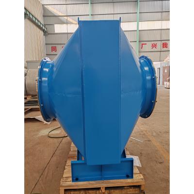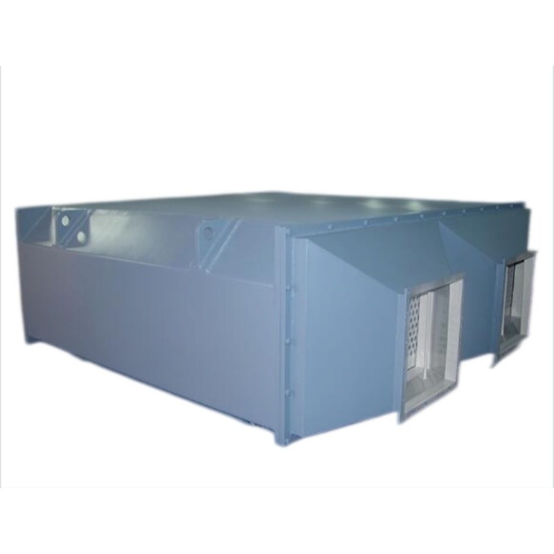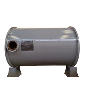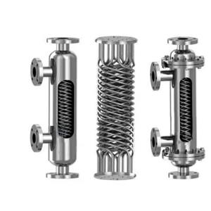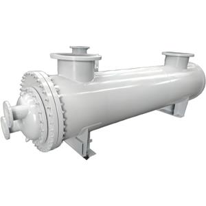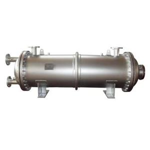
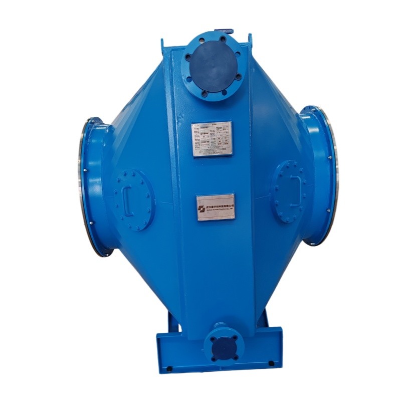
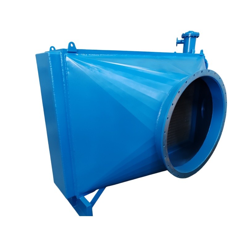
Flue Gas Cooler Heat Exchanger Waste Heat Recovery Boiler

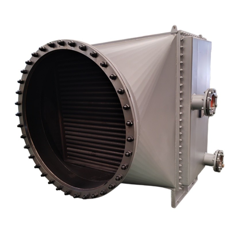
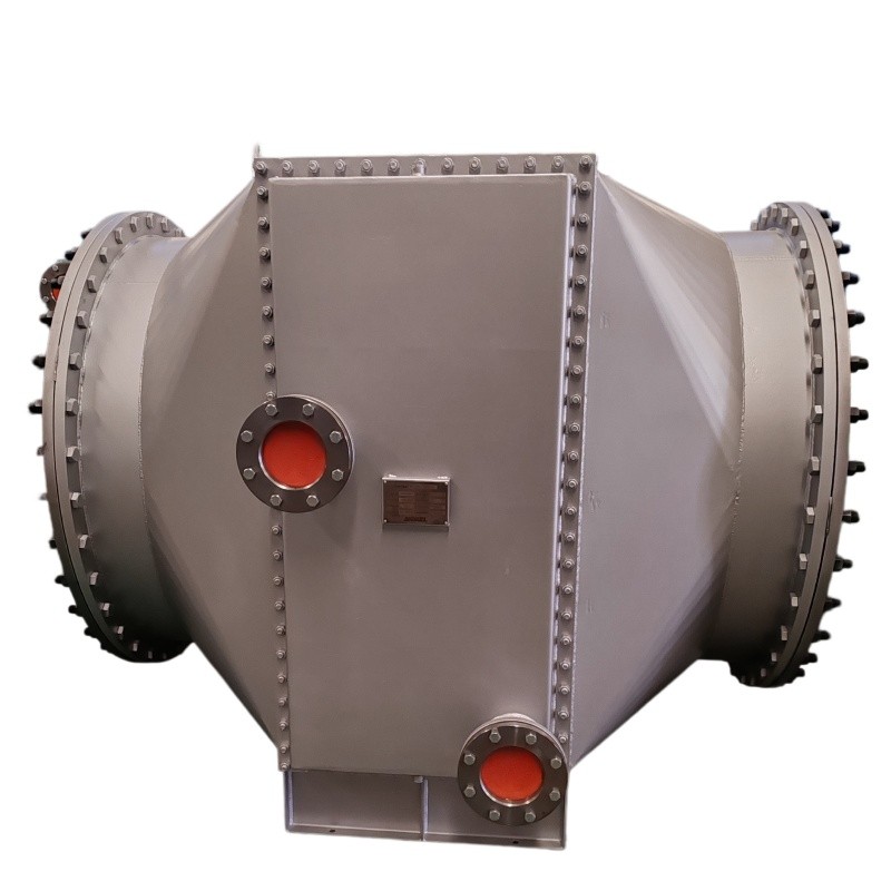
- OEM/ODM
- CHINA
1.Superior resistance to high-temperature sulfidation and oxidation.
2.Prevents freeze damage and internal corrosion during maintenance shutdowns.
3.Prevents freeze damage and internal corrosion during maintenance shutdowns.
4.Ensures precise alignment with existing plant piping, reducing on-site installation time and gasket stress.
5.Extends the life of the carbon steel shell in harsh industrial atmospheres.
Flue Gas Waste Heat Recovery Cooler
| Parameter Category | Shell Side (壳程) | Tube Side (管程) |
| Medium | Flue Gas | Cooling Water |
| Temperature - Inlet | 514 °C | 60 °C |
| Temperature - Outlet | 181 °C | 80 °C |
| Design Temperature | 550 °C | 90 °C |
| Flow Rate | 18,419 Nm3/h | ≈ 97 Nm3/h |
| Design Pressure | 5 KPa (0) | 0.5 MPa (0) |
| Allowable Pressure Drop | 400 Pa | — |
| Actual Pressure Drop | 250 Pa | — |
| Heat Transfer Area | 290m2 | |
Real-World Application Scenarios
This Flue Gas Waste Heat Recovery Cooler is engineered for harsh industrial environments where reliability is non-negotiable.
1.Waste Incineration Plants (Incinerator Flue Gas Cooling): In municipal solid waste (MSW) incinerators, flue gas exits the combustion chamber at extreme temperatures. This cooler acts as a critical interface, reducing
the gas temperature from 514°C to 181°C. This specific temperature drop is essential for protecting downstream selective catalytic reduction (SCR) systems and baghouse filters from thermal damage, ensuring continuous compliance with environmental emission standards.
2.Industrial Boiler Heat Recovery (Boiler Flue Gas Cooler): In heavy manufacturing facilities, exhaust from industrial boilers often carries recoverable thermal energy. By integrating this 290m² heat exchanger, plants can preheat boiler feedwater or generate hot water for facility heating. The 60°C to 80°C temperature rise in the cooling water loop represents a direct recovery of waste heat that would otherwise be lost to the atmosphere.
3.High-Temperature Process Gas Cooling: In chemical or metallurgical processes where gas streams reach 500°C+, this unit provides a robust cooling solution. The Q235B shell provides structural stability while the internal S30408 tube bundle handles the thermal load, ensuring process safety and equipment longevity.
Engineering Pain Points and Technical Solutions
Pain Point 1: Thermal Fatigue and Material Degradation under Extreme Temperature Fluctuations
Industrial processes often generate flue gas at temperatures exceeding 500°C. Standard carbon steel structures exposed to a 514°C inlet temperature will undergo rapid oxidation and creep, leading to premature equipment failure.
Solution: This Flue Gas Cooler utilizes S30408 austenitic stainless steel for all heat exchange tubes (specification: Φ25X2) and 304 stainless steel for fins. With a design temperature rated at 550°C, the material selection provides a verified thermal margin. The high chromium/nickel content in S30408 resists scaling and maintains structural integrity during the continuous 514°C to 181°C cooling cycle, effectively preventing thermal fatigue cracking.
Pain Point 2: Incomplete Drainage Leading to Tube Rupture in Cold Climates
In many industrial facilities, particularly those in regions with temperature fluctuations, residual water inside heat exchanger tubes during shutdowns can freeze. The resulting volumetric expansion exerts immense pressure, causing catastrophic tube rupture.
Solution: The design strictly incorporates a "complete internal water drainage" requirement. The tube-side slope and connection seat geometry are engineered to ensure that no stagnant water remains in the tube bundle after operation. Additionally, all connection seats are factory-equipped with screw plugs to seal the system against external contaminants during storage or idle periods.
Pain Point 3: Pressure Drop Management in Low-Pressure Flue Gas Systems
Excessive backpressure in the shell side can force the main exhaust fan to work harder, drastically increasing plant energy consumption and operational costs.
Solution: The Flue Gas Waste Heat Cooler is engineered with a verified actual pressure drop of only 250 Pa (against an allowable limit of 400 Pa). By maintaining a low resistance flow path, the system minimizes the parasitic load on the plant’s induced draft fan, ensuring that the heat recovery process does not compromise the primary process flow.
Frequently Asked Questions (FAQ)
Q1: What is the significance of the "complete drainage" design for this Flue Gas Cooler?
A: The tube bundle and connection seats are engineered to allow all internal cooling water to drain completely when the unit is taken offline. This prevents water from stagnating inside the tubes, which is critical for avoiding freeze damage in cold environments and preventing internal corrosion during long-term shutdowns. All connection seats are also factory-fitted with screw plugs for additional protection.
Q2: How does the 250 Pa pressure drop benefit my plant operations?
A: The shell side actual pressure drop is verified at 250 Pa, which is well within the 400 Pa allowable limit. A lower pressure drop means the induced draft fan in your exhaust system does not need to work as hard to push flue gas through the cooler. This directly reduces electricity consumption and wear on the fan motor, lowering your operational costs.
Q3: Can this Flue Gas Waste Heat Recovery Cooler be customized for different flange connections?
A: The current design features flanges with holes arranged symmetrically (across-center). This ensures proper alignment with standard piping. For specific project requirements, the flange drilling pattern can be adjusted during the manufacturing phase. Please provide your piping isometric drawings for verification.
Q4: What is the purpose of the hydrostatic test at 1.25 times design pressure?
A: This is a mandatory safety verification. The tube side is tested at 0.625 MPa and the shell side at 6.25 KPa (1.25x their respective design pressures). The unit must hold this pressure for 30 minutes with no leakage, no abnormal sounds, and no visible deformation. This proves the weld integrity and pressure boundary strength before the unit leaves the factory.
Q5: Is the GB/T 14296-2008 standard recognized for international projects?
A: GB/T 14296-2008 is the Chinese national standard for air coolers and heat exchangers. It covers design, materials, manufacturing, and testing requirements. Many international engineering, procurement, and construction (EPC) firms operating in Asia, the Middle East, and Africa accept this standard. For projects requiring ASME or EN standards, a design review and material substitution can be discussed based on project specifications.