What Are Heat Exchanger Heat Transfer Enhancement Technologies? One Article to Understand High-Efficiency Heat Exchangers
Under the same heat load, can a heat exchanger be made smaller and more cost-effective? This is a calculation constantly performed by both design institutes and plant sites. Essentially, enhanced heat transfer aims to improve heat transfer capacity, reduce heat transfer area, and lower energy consumption—all while keeping the process temperature difference and operational requirements unchanged. There are only three approaches: modifying the heat transfer surface, controlling fouling, and selecting materials.
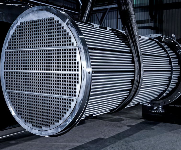
At the site of the heat exchanger bundle extraction inspection, how the shell side is supported and how the flow is directed often impact operation more significantly than the tube dimensions themselves.
First, clarify: which side actually needs enhancement?
Q = K · A · Δtm. To increase heat transfer, you either expand the area or raise the overall heat transfer coefficient.
K is the result of four thermal resistances in series: inside-tube convection, outside-tube convection, tube wall conduction, and fouling on both sides. The side with the largest share is the one that needs enhancement.
The most common pitfall in selection is expending effort on the side that does not control the total thermal resistance—it looks busy, but it is useless.
I. Modifying the Heat Transfer Surface: Four Mainstream Structures
1.Threaded tubes: The 'standard component' for outside-tube enhancement
The definition in GB/T 28713.1-2012 is clear: it is an integrally low-finned tube manufactured by circumferential cold rolling on the outer surface of a seamless steel tube. According to Table 1, for a 25×2.5 mm tube, the fin efficiency ratio η shall not be less than 1.6 to 2.8; the denser the pitch, the higher the ratio. The applicable scope is also explicitly stated: it is intended for applications where the total shell-side thermal resistance (including both the fluid film and fouling resistances) is the controlling resistance. It is not suitable for conditions with high solid dust content or a high coking tendency on the shell side. Therefore, the claim that 'threaded tubes can suppress fouling' must be taken with a grain of salt—the standard, in fact, delineates precisely where they are prohibited.
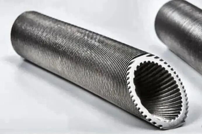
Cold-rolled spiral-grooved enhanced tube: external fins expand the surface area, while internal grooves disturb the boundary layer.
The trade-off is pressure drop. Clause 4.3.1.1 of GB/T 151-2014 lists 'allowable pressure drop' as one of the process design conditions—before adopting enhanced tubes, make sure the margins of pumps and fans are thoroughly calculated.
2.Tube Inserts: Leveraging the Tube Side with a Twisted Tape
Inserting wire mesh, spiral wire, fins, or a twisted tape into the tube disrupts the laminar boundary layer, thereby increasing the tube-side convective heat transfer coefficient. When tube-side thermal resistance dominates, this offers the best cost-performance ratio.
However, note the stance of the standard system. Clause 5.4.2 of GB/T 151-2014 permits the use of enhanced heat transfer tubes, listing only three categories: GB/T 24590 special-shaped tubes, and GB/T 28713.1, 28713.2, and 28713.3. In other words, tube inserts currently have no corresponding national product standard. Their selection relies on design calculations and experimental verification, and both pressure drop and cleaning costs must be factored in.
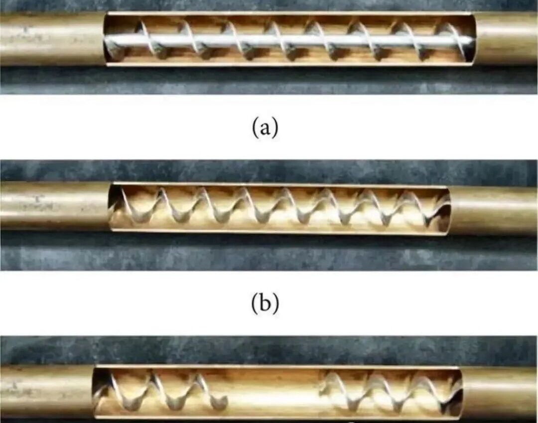
(a) Internal twisted-tape insert (b) Continuous internal spiral groove (c) Discontinuous internal spiral — three scales of enhancement on a single tube
3. Rod Baffles: Replacing 'Obstruction' with 'Support'
Segmental baffles force shell-side fluid to cross-flow through the tube bundle, delivering high heat transfer but at the cost of high pressure drop and susceptibility to flow-induced vibration.
Rod baffles take a different approach: four rods, spaced at 90° intervals around the circumference, securely cradle each tube while allowing fluid to flow longitudinally. Clause 6.8.2.6 of GB/T 151-2014 explicitly permits the use of rod baffles and other baffle-support structures. This reduces pressure drop and improves support conditions.
However, the claim that 'rod baffles eliminate vibration problems' is unfounded. Clause 6.8.2.3.3 stipulates that unsupported spans shall not exceed the limits in Table 6-31, and spans must be further reduced in cases of fluid pulsation. Annex C provides the calculation criteria for flow-induced vibration—even with rod baffles, no step in the verification process can be omitted."
4. Helical Baffles: Altering the Flow Regime
The helical baffle heat exchanger is an improved variant of the shell-and-tube heat exchanger. Its design core lies in the unique helical baffle channel structure within the shell side, aimed at optimizing flow, enhancing heat transfer, and reducing pressure drop—making it particularly suitable for heating high-viscosity crude oil and similar media. The tube bundle skeleton is assembled from several sector-shaped baffles, each approximately one-quarter of the shell-side cross-sectional area, arranged in a continuous helical pattern starting from the fluid inlet.
This structure guides the shell-side fluid to flow continuously and smoothly in a helical path around the tube bundle center, completely replacing the traditional transverse 'Zigzag' cross-flow induced by segmental baffles and the longitudinal flow pattern of rod baffle heat exchangers. Depending on process requirements, this type of heat exchanger is available in single-shell-pass and double-shell-pass configurations; the axial overlap design of the baffles further optimizes support and flow distribution. The helix inclination angle (typically ranging from 25° to 45°) is an adjustable design parameter used to accommodate different operating conditions.
The helical baffle heat exchanger features a flexible structure and is compatible with various enhanced heat transfer tube types, including plain tubes, corrugated tubes, threaded tubes, spiral corrugated tubes, and internally corrugated and externally threaded tubes.
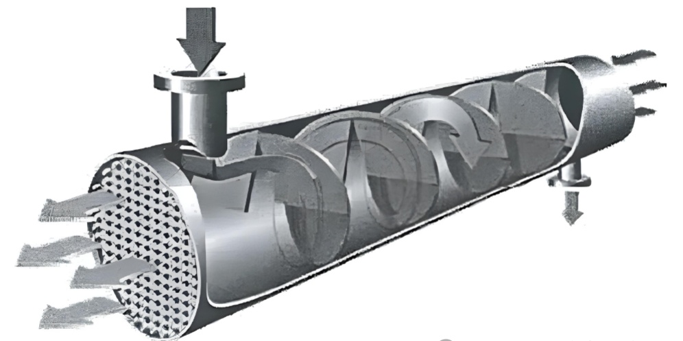
Internal Structure of Helical Baffle Heat Exchanger: Altering the Medium Flow State
5. Corrugated and Bellows Tubes: Efficiency First, Parameters Speak
Featuring annular ribs on both inner and outer walls, these tubes enhance both tube-side and shell-side performance simultaneously, offering significant advantages in compact applications. Key parameters must be strictly observed:
GB/T 28713.2-2012: Austenitic stainless steel corrugated tubes; nominal pressure ≤ 4.0 MPa; operating temperature > -20℃ and < 450℃; nominal tube blank thickness 0.6–1.2 mm; wall thickness reduction ≤ 15%.
GB/T 28713.3-2012: Bellows tubes are classified into two types—thin-wall Type B (0.5–1.0 mm) and thick-wall Type H (>1.0–3.5 mm).
The claim that 'corrugated tubes have a wall thickness of only 0.1 mm and leak upon vibration' is a widespread misinterpretation. While thin-wall tubes do have fatigue limitations, the correct solution for high-pressure, high-temperature, highly corrosive, or high inlet velocity applications is to select Type H bellows tubes—or switch to an entirely different structure.
II. Fouling Control: Managing the Invisible Thermal Resistance
Fouling is not an unexpected occurrence that only appears after operation begins; it should be accounted for at the design stage. GB/T 151-2014, Clause 4.3.2.2 stipulates that fouling resistance shall be determined in accordance with Annex E.
Fluid velocity is the first line of defense. HG/T 20690-2000, Clause 3.1.6 specifies that tube-side circulating cooling water velocity should not be less than 0.9 m/s, shell-side velocity should not be less than 0.3 m/s, and heat flux density should not exceed 58.2 kW/m². The rationale provided in the clause explanation is straightforward—heat exchangers operating below 0.3 m/s universally suffer from fouling and under-deposit corrosion.
Does this mean faster is always better? The same explanatory note also states: the upper limit must consider erosion-corrosion of the material; 'this is generally accounted for in equipment design,' and the standard does not specify further limits. Speed has its price.
Water quality and chemical treatment should follow Clauses 3.1.7, 3.2.1, and 3.4.1: for open systems, annual fouling resistance should range from 1.72×10⁻⁴ to 3.44×10⁻⁴ m²·K/W; the concentration ratio should not be less than 3.0; chemical formulations should be determined based on dynamic simulation tests or operational experience from similar conditions.
The reason magnetic and electronic descaling technologies remain controversial is precisely because their effectiveness is highly dependent on water quality and operating conditions. Whether they can be used must be justified by verification results.
Cleaning must also be governed by metrics. SH/T 3547-2011, Table 2: carbonate scale removal rate ≥90%; sulfate and silicate scale ≥85%; rust and oil sludge ≥95%. Table 1 stipulates corrosion rates: carbon steel ≤6 g/(m²·h), stainless steel ≤2 g/(m²·h). Clause 7.1 further requires a complete passivation film after cleaning.
III. Material Selection: Don't Focus Solely on Thermal Conductivity
Heat exchanger tube materials shall be selected per GB 150.2-2011 and GB/T 151-2014, Clause 5.4.1, with thermal conductivity referenced from Annex F. However, wall thermal resistance is merely one item in the series of thermal resistances; wall thickness and convective coefficients on both sides usually dominate.
What truly makes the difference is corrosion resistance, and it has a quantified benchmark: HG/T 20690-2000, Clause 3.1.7 specifies that the corrosion rate of carbon steel tubes should be less than 0.10 mm/a, while copper, copper alloys, and stainless steel tubes should be less than 0.005 mm/a—a difference of two orders of magnitude. This calculation is far more significant than the minor differences in thermal conductivity.
II. Fouling Mitigation: Controlling the Invisible Resistance
Fouling is not a post-operational surprise; it must be factored in during design. Clause 4.3.2.2 of GB/T 151-2014 dictates that fouling resistance be taken from Annex E.
Velocity is the primary barrier. Clause 3.1.6 of HG/T 20690-2000 requires tube-side cooling water velocity ≥0.9 m/s, shell-side ≥0.3 m/s, and heat flux ≤58.2 kW/m². The accompanying note is explicit: exchangers below 0.3 m/s commonly exhibit fouling and under-deposit corrosion.
But is higher velocity always better? The same note clarifies that the upper limit must prevent erosion-corrosion based on material—'typically addressed in equipment design'—so no further limits are set. Higher velocity incurs costs.
Water quality and treatment agents follow Clauses 3.1.7, 3.2.1, and 3.4.1: open systems should maintain fouling resistance between 1.72×10⁻⁴ and 3.44×10⁻⁴ m²·K/W; concentration cycles ≥3.0; and chemical formulations should derive from dynamic simulation or analogous operational data.
Magnetic and electronic descaling remain debated because efficacy heavily depends on water quality and conditions. Applicability must be proven by verification.
Cleaning requires quantifiable indicators. SH/T 3547-2011, Table 2: carbonate scale removal ≥90%; sulfate/silicate scale ≥85%; rust/oil sludge ≥95%. Table 1 limits corrosion to ≤6 g/(m²·h) for carbon steel and ≤2 g/(m²·h) for stainless steel. Clause 7.1 mandates a complete passivation film post-cleaning.
III. Material Selection: Beyond Thermal Conductivity
Tube materials are selected per GB 150.2-2011 and Clause 5.4.1 of GB/T 151-2014, with conductivity from Annex F. Yet wall resistance is just one series component; wall thickness and convection often matter more.
Corrosion resistance creates the real gap, quantified by HG/T 20690-2000, Clause 3.1.7: carbon steel corrosion rate <0.10 mm/a; copper and stainless steel <0.005 mm/a—two orders of magnitude apart. This factor outweighs minor thermal conductivity differences.
II. Controlling Fouling: Keeping That Invisible Thermal Resistance in Check
Fouling isn't something unexpected that only shows up after you start running; it should have a place in the design phase. GB/T 151-2014, Clause 4.3.2.2 says fouling resistance should be taken according to Annex E.
Flow velocity is the first gate. HG/T 20690-2000, Clause 3.1.6: tube-side circulating cooling water velocity shouldn't be less than 0.9 m/s, shell-side shouldn't be less than 0.3 m/s, and heat flux shouldn't be more than 58.2 kW/m². The explanation is pretty blunt—heat exchangers with velocity below 0.3 m/s generally have fouling and under-deposit corrosion.
So is faster always better? That same note also says: the upper limit needs to consider material to prevent erosion-corrosion, 'this is generally already considered in equipment design,' so the standard doesn't set a limit. Going fast has its costs.
Water quality and chemicals follow Clauses 3.1.7, 3.2.1, 3.4.1: for open systems, annual fouling resistance should be 1.72×10⁻⁴ to 3.44×10⁻⁴ m²·K/W; concentration ratio shouldn't be less than 3.0; chemical formulas should be set by dynamic simulation tests or experience from similar conditions.
The reason magnetic and electronic descaling keep being debated is exactly because the effect highly depends on water quality and working conditions. Whether it can be used has to be backed by verification results.
Cleaning also needs metrics. SH/T 3547-2011 Table 2: carbonate scale removal rate no less than 90%, sulfate and silicate scale no less than 85%, rust and oil sludge no less than 95%; Table 1 says corrosion rate for carbon steel ≤6 g/(m²·h), stainless steel ≤2 g/(m²·h); Clause 7.1 also requires a complete passivation film after cleaning.
III. Choosing Materials: Don't Just Stare at Thermal Conductivity
Heat exchanger tube materials are selected according to GB 150.2-2011 and GB/T 151-2014 Clause 5.4.1, with thermal conductivity checked in Annex F. But tube wall resistance is just one item in the series of thermal resistances; wall thickness and convection on both sides usually count for more.
What really makes the difference is corrosion resistance, and there's a quantified standard: HG/T 20690-2000 Clause 3.1.7 says carbon steel tube wall corrosion rate should be less than 0.10 mm/a, copper, copper alloys, and stainless steel tubes should be less than 0.005 mm/a. Two orders of magnitude. This calculation matters way more than those small differences in thermal conductivity.
Enhanced heat transfer has never been as simple as merely 'maximizing the heat transfer coefficient.' It is an exercise in trade-offs: area, coefficient, fouling, pressure drop, and reliability—all five must be weighed together.
For new units, effort should be invested in structure and materials at the design stage; for existing equipment, fouling and pressure drop should be assessed first before deciding whether to modify the structure, perform cleaning, or adjust operations.
The main reason high-efficiency heat exchangers have not been widely adopted in current refining and petrochemical plants—especially in oil refining units—is that media such as crude oil and circulating water are prone to fouling, which impairs heat transfer and proves counterproductive. So, tell us about successful cases of high-efficiency heat exchanger retrofits in your plant.