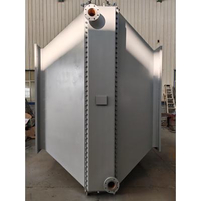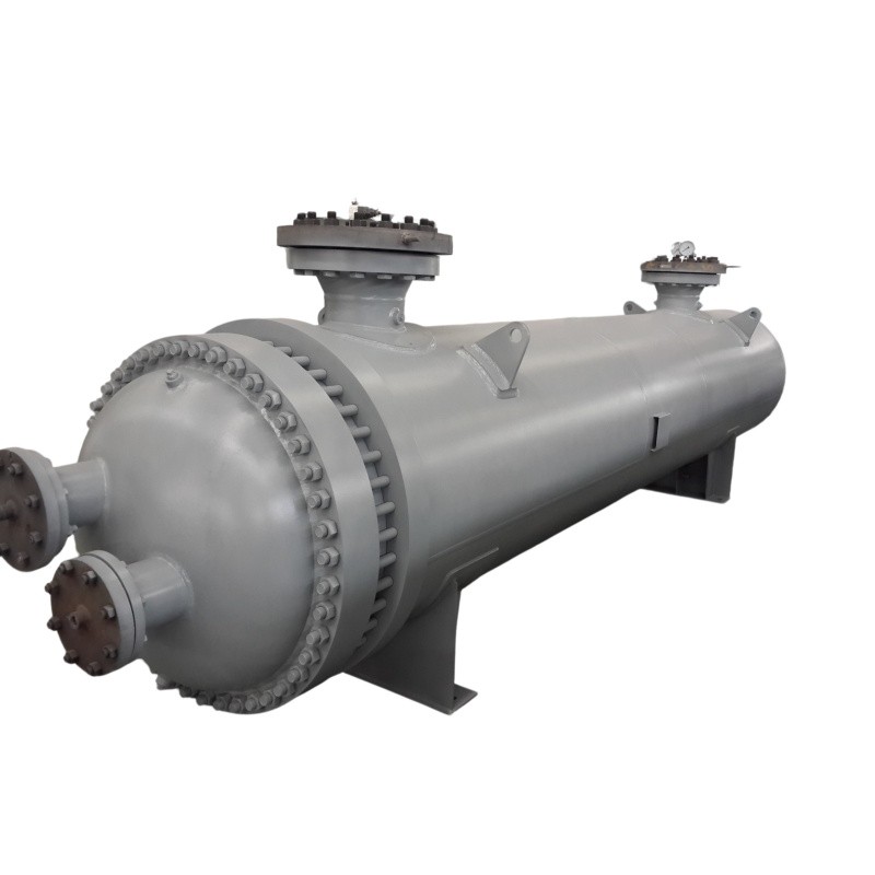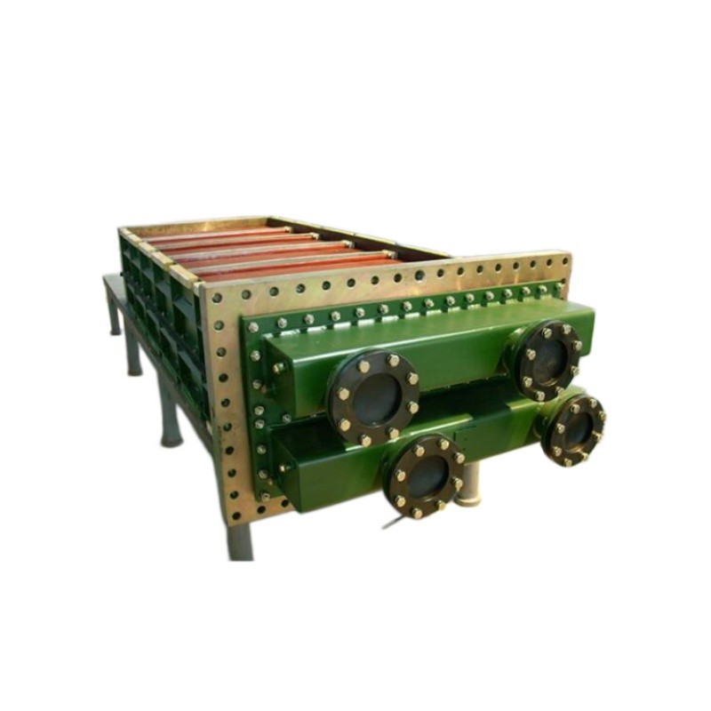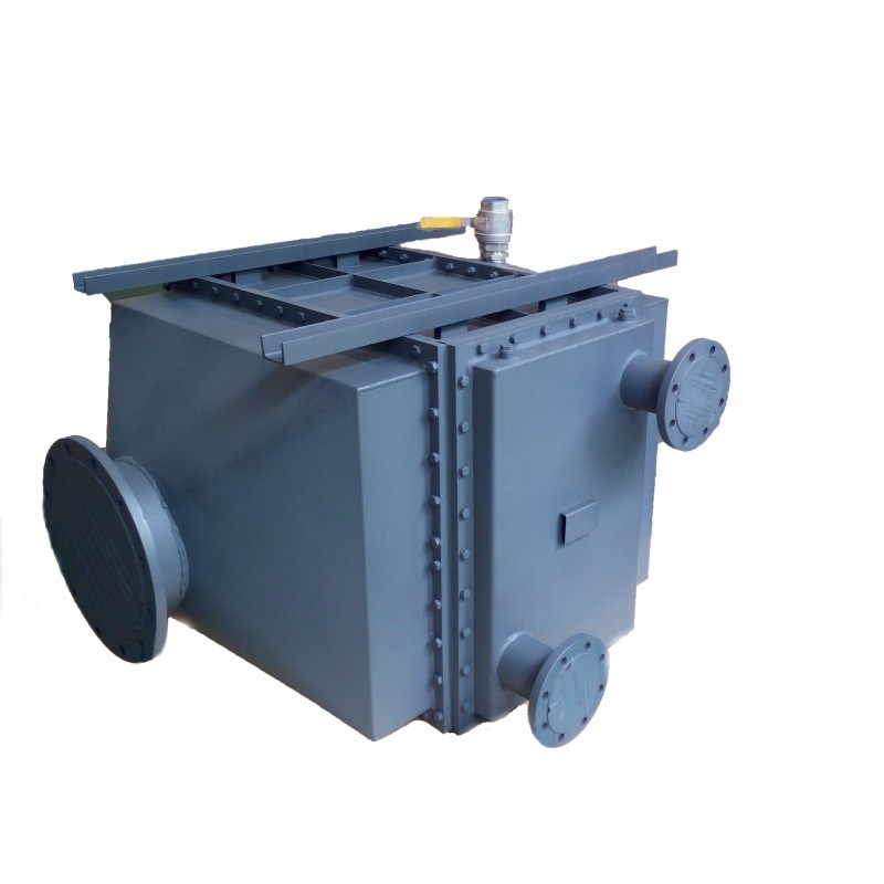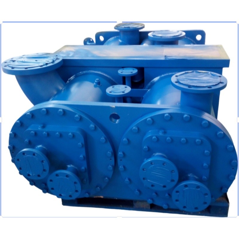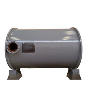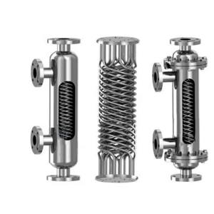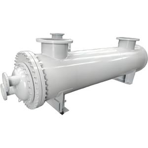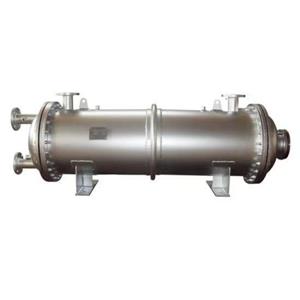
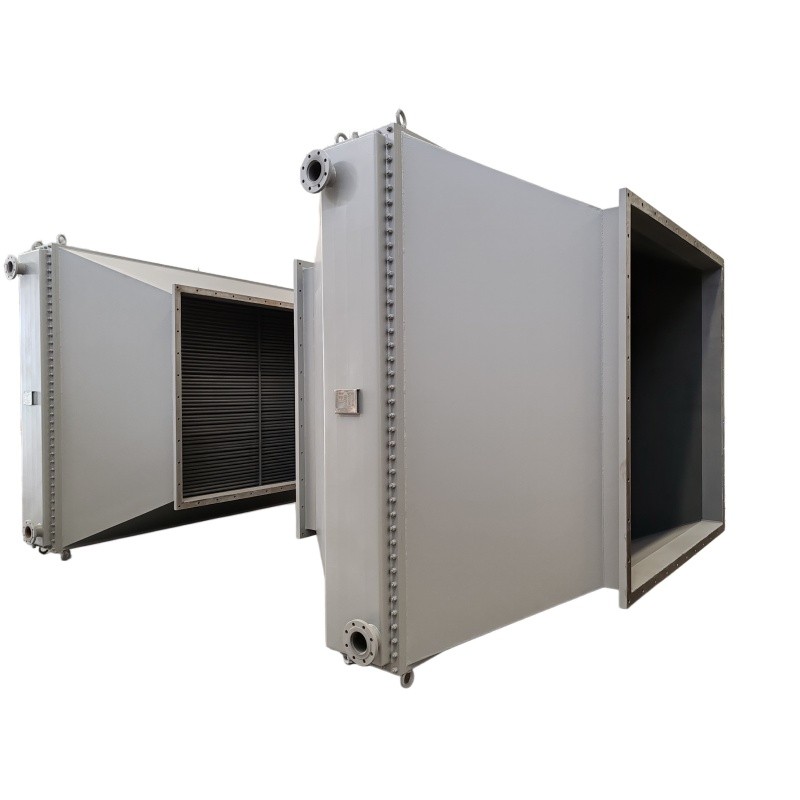
Industrial Finned Tube Heat Exchanger Bimetallic Composite

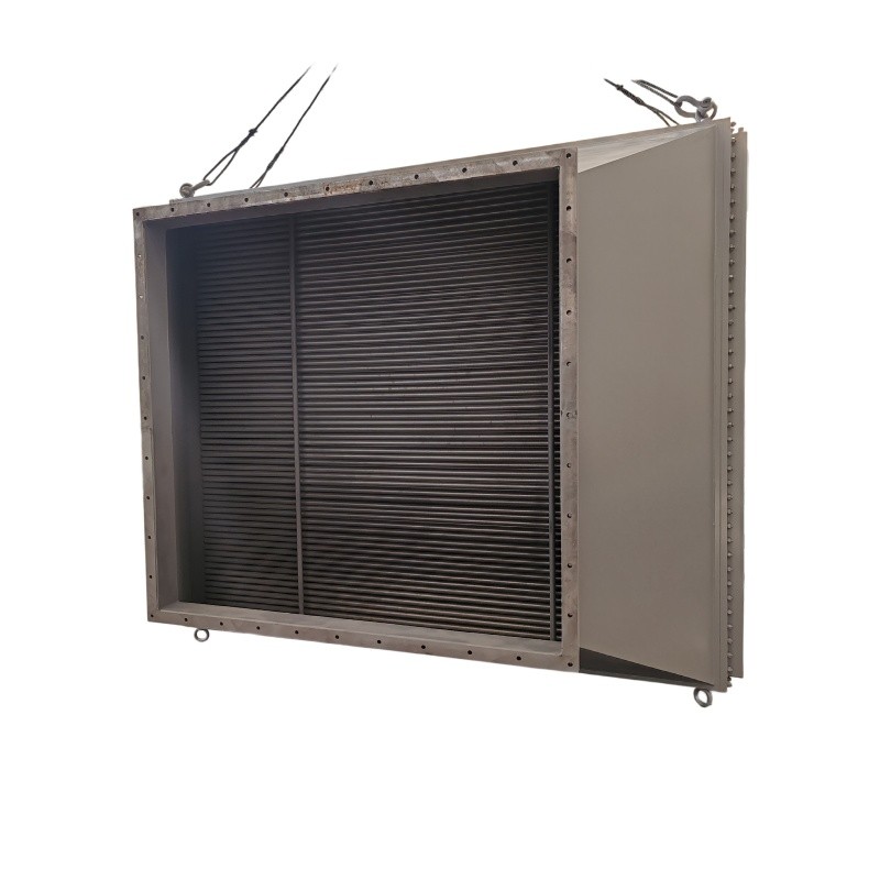
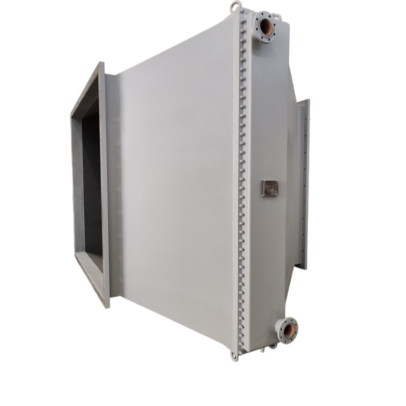
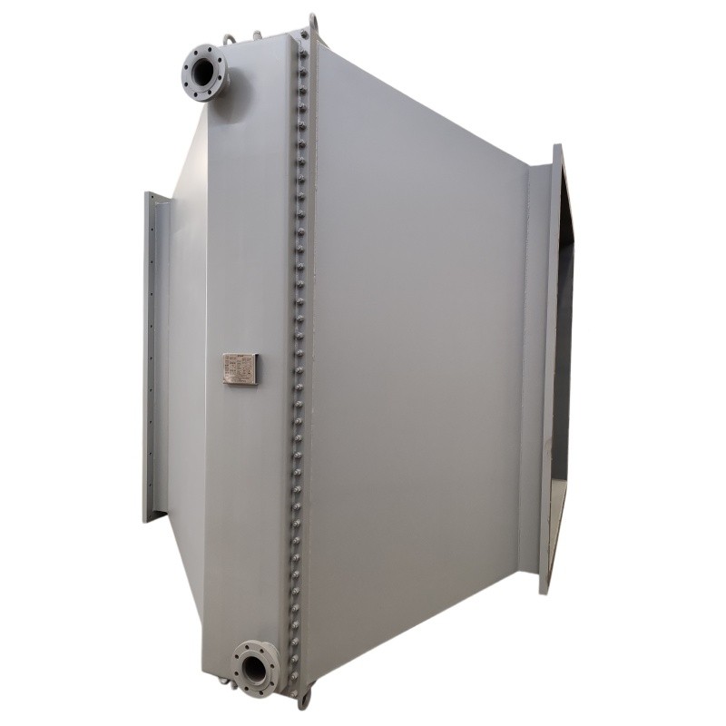
- OEM/ODM
- CHINA
1.Steel aluminum composite finned tube with metallurgical bonding; eliminates interfacial gaps and ensures uniform heat transfer.
2.6-pass tube side; balances velocity and pressure drop at 120 kPa, achieving optimal heat transfer coefficient.
3.Strength welding process; full-penetration weld provides superior resistance to fatigue and creep.
4.15-year design life with 1mm corrosion allowance on both sides; engineered for extended service in harsh environments.
Industrial Finned Tubeer for Flue Gas & Water Heat Exchang
| Parameter Name | Tube Side (管程) | Shell Side (壳程) | |
| Medium Name | Circulating Water | Flue Gas | |
| Medium Characteristics | Non-toxic,Non-explosive | Non-toxic,Non-explosive | |
| Operating Pressure | MPa | 0.35 | 0.01 |
| Design Pressure | MPa | 0.6 | 0.02 |
| Pressure Drop | kPa | 120 | 0.286 |
| Operating Temperature (Inlet/Outlet) | ℃ | 72/>90 | 140/ 110 |
| Design Temperature | ℃ | 120 | 180 |
| Corrosion Allowance | mm | 1 | 1 |
| Number of Passes | 6 | 1 | |
| Heat Transfer Area | ㎡ | 769 | |
| Heat Exchanger Tube Spec. | mm | Composite Finned Tube | |
| Tube-to-Tubesheet Connection | Strength Welding | ||
| Net Weight | kg | 4200 | |
| Design Life | Years | 15 | |
Engineering the Solution: Three Critical Pain Points Resolved
When specifying thermal equipment for high-temperature gas-to-liquid transfer, procurement teams consistently face three operational bottlenecks. Our industrial finned tube heat exchanger addresses each with measurable engineering precision。
Pain Point 1: Low Heat Transfer Efficiency on the Flue Gas Side
In many industrial heat recovery systems, flue gas has a much lower heat transfer coefficient than liquid media such as circulating water. If the gas-side surface area is insufficient, the exchanger may meet initial performance expectations but gradually underperform as fouling, dust deposition, or surface oxidation develops.
Solution:
This unit uses composite finned tubes with a total heat exchange area of 769 m². The finned structure increases the effective heat transfer surface on the gas side, reducing the thermal resistance that typically limits flue gas heat recovery. This design is especially relevant for applications where the shell-side medium is flue gas at 140°C inlet / 110°C outlet, and the tube-side medium is circulating water at 72°C inlet / >90°C outlet.
Pain Point 2: Long-Term Reliability Under Continuous Thermal Exposure
Heat exchangers handling flue gas and circulating water often operate under continuous thermal cycling, pressure variation, and long service demands. A unit that is not designed for sustained operation may require early inspection, unplanned shutdowns, or premature replacement.
Solution:
The exchanger is designed for a 15-year service life, with a design temperature of 120°C on the tube side and 180°C on the shell side. The working pressure is 0.35 MPa on the tube side and 0.01 MPa on the shell side, while the design pressure is 0.6 MPa and 0.02 MPa, respectively. These parameters indicate that the unit is dimensioned with a safety margin above normal operating conditions, which supports long-term operational stability in industrial heat recovery environments.
Pain Point 3: Maintenance Cost and System Downtime
For plant operators and EPC contractors, maintenance cost is not only about spare parts. It includes system shutdown time, labor, cleaning access, inspection complexity, and the risk of production interruption. A heat exchanger with poor mechanical joint reliability or inadequate corrosion allowance can increase lifecycle costs even if its initial price appears competitive.
Solution:
This bimetallic finned tube heat exchanger configuration uses strength welding for the connection between the heat exchange tubes and the tube sheet. Compared with joints that rely only on expansion or weak mechanical attachment, strength welding improves resistance to thermal cycling, vibration, and long-term joint degradation. The design also includes a corrosion allowance of 1 mm on both the tube side and shell side, providing additional material reserve for long-term operation.
Typical Application Scenarios
1.Flue Gas Heat Recovery in Industrial Process Systems
In industrial plants where flue gas exits equipment at around 140°C, a Combined Finned Tube Heat Exchanger can be used to recover usable thermal energy. The shell-side flue gas cools from 140°C to 110°C, while circulating water on the tube side is heated from 72°C to above 90°C. This makes the unit suitable for process water preheating, plant heat recovery loops, and systems where low-grade thermal energy can be reused.
2.Circulating Water Heating Systems
For facilities that operate closed-loop circulating water systems, this industrial finned tube heat exchanger can serve as a heat recovery unit between flue gas and water. The 6 tube passes increase water-side velocity, which helps maintain a higher heat transfer coefficient. The 120 kPa tube-side pressure drop should be confirmed against the existing pump head before integration.
3.Low-Pressure Gas-Side Thermal Systems
The shell-side working pressure of 0.01 MPa and design pressure of 0.02 MPa indicate that this exchanger is intended for low-pressure gas service rather than high-pressure gas containment. It is suitable for applications where the flue gas path is open or near-atmospheric, and where the main engineering requirement is efficient heat transfer rather than high-pressure gas sealing.
Frequently Asked Questions (FAQ)
Q1: Can the finned tube exchanger be customized for different inlet/outlet temperatures?
Yes. The current design operates with water from 72°C to >90°C and flue gas from 140°C to 110°C. For different temperature ranges, we can adjust the number of tube passes (currently 6) or fin density. The strength welding and steel-aluminum composite construction remain unchanged, ensuring joint integrity across a broad thermal operating window.
Q2: What is the lead time for a 4,200 kg unit with 769 m² heat transfer area?
Standard production lead time is 8–12 weeks from order confirmation, depending on material availability. The steel-aluminum composite tubes require a dedicated finning schedule. We recommend confirming specifications early to align with your project timeline.
Q3: How does the 1 mm corrosion allowance impact maintenance schedules?
The 1 mm allowance is calculated based on a conservative corrosion rate for non-toxic, non-explosive flue gas and circulating water. In most industrial environments, this eliminates the need for internal lining or cathodic protection, reducing both CAPEX and ongoing maintenance costs over the 15-year design life.
Q4: Is this industrial finned tube heat exchanger suitable for high-sulfur flue gas?
The current design is rated for non-corrosive flue gas. For high-sulfur or acidic gas streams, we recommend upgrading the tube material to stainless steel or applying a protective coating. The strength welding process is compatible with a wide range of material combinations; consult our engineering team for a material selection review.
Q5: What information should buyers confirm before placing an order?
Buyers should confirm the following items with the supplier:
Applicable design code and pressure vessel category
Material specifications for tubes, fins, shell, and tube sheet
Welding procedure and inspection method
Pressure test and leakage test requirements
Dimensional drawing and foundation load data
Packing method for a 4200 kg unit
Lead time, shipping terms, and spare parts availability